

 Get a Quote
What Your Custom Injection Mold Supplier Needs Before the Tool Drawing Is Released
Which file wins when the purchasing attachment, the solid model and the engineer’s latest PDF disagree? Resolve that question before releasing a custom injection mold supplier to manufacture the tool. For a made-to-drawing project, a controlled definition is the foundation of useful tooling, reliable samples and a quotation that reflects the intended component.
JY Pretech works from customer designs to review mold construction, produce tooling and supply molded components. Our project process begins with the model and requirements. Buyers preparing a new housing, fitting or technical component should establish the approved geometry, material, surface expectations and delivery object first. The tooling and mold components service is a useful starting point when the mold itself will be delivered to another plant.
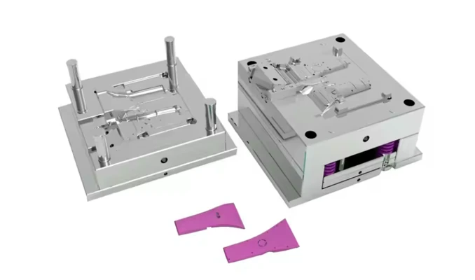
Give the custom injection mold supplier one controlled product definition
A solid model and a drawing perform different jobs. The STEP or IGS model establishes geometry that can be reviewed and used in manufacturing preparation. A dimensioned 2D PDF can identify critical interfaces, tolerances, datums, cosmetic regions and notes that cannot be inferred reliably from the shape alone. Both should describe the same released revision.
Imagine an industrial controller cover whose connector opening moves during quotation. The change also shifts a nearby rib and reduces access around a screw boss. Sending a replacement model without explaining the change leaves the toolmaker to discover its significance. A short revision description helps JY Pretech review the affected mold features, rather than treating a new file as an otherwise identical shape.
STEP geometry and the 2D PDF should agree on the housing revision
Name the model and drawing with the component identifier and revision. Identify the document that controls each requirement if your engineering system intentionally separates geometry from tolerancing. Do not leave a note such as “use latest drawing” unresolved when several attachments exist. The manufacturing release should make the intended configuration identifiable without relying on a conversation remembered by one person.
For an enclosure set, control each component separately. The cover and base may advance through different revisions, while their shared mounting pattern must remain compatible. If JY Pretech will mold only the cover, provide the mating definition needed to understand that pattern. If the complete set is included, state which combinations must be demonstrated during sample approval.
Insert drawings need the supplied hardware condition
An insert-molded component adds another controlled item. A nominal metal shape does not explain whether hardware is supplied by the customer or purchased within the manufacturing scope. Identify the insert drawing, material or part reference, the locating features and any surfaces that must remain free of plastic. Review handling and inspection in the condition that will actually enter the tool.
JY Pretech’s manufacturing range includes insert molding, overmolding and two-shot molding. These services allow different ways to build an interface, but the order needs to say which sequence is intended. A separately molded substrate placed into another tool and a two-shot production arrangement are different proposals. The final outside shape alone does not define the equipment or tooling responsibility.
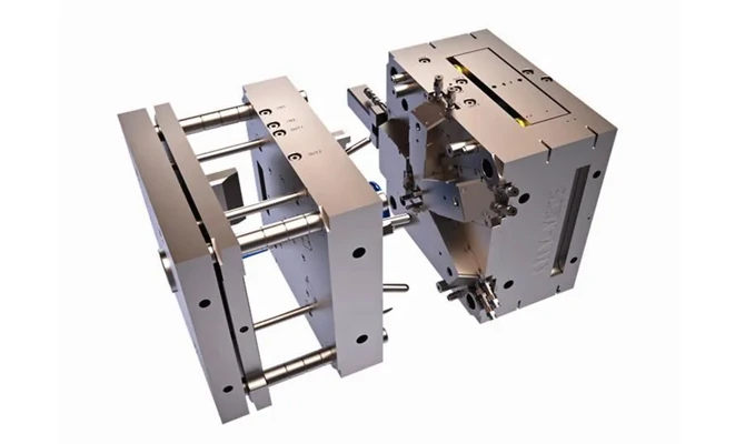
Translate component requirements into a custom mold supply agreement
The tool drawing should connect the buyer’s component requirements to the proposed manufacturing arrangement. JY Pretech’s review addresses gate location, parting lines, draft, wall thickness and ejection. Each can affect the delivered part. Approving a mold layout therefore means more than acknowledging that the tool can close around the model.
A latch undercut needs an agreed release mechanism
A concealed latch can require a different release approach from the surrounding wall. The rapid tooling service describes hand-loaded inserts for suitable undercuts and hydraulic sliders for appropriate deeper features. Discuss the proposed mechanism against the expected program. The preferred development arrangement may differ from the preferred solution after quantities and geometry become stable.
Do not mark a latch “noncritical” merely because it is hidden. Its engagement may determine whether a service technician can open the enclosure without damaging it. Explain that function, identify the mating feature and state what the sample must demonstrate. This gives the toolmaker a reason to protect the geometry while evaluating manufacturability.
The engineering principles in the Protolabs molding design guidance provide background on walls, draft and undercuts. Use such guidance to understand the tradeoffs, then approve the actual JY Pretech proposal. A general design recommendation is not evidence that a particular latch will survive its application or that a selected mechanism suits every production quantity.
Component approval: geometry, material, functional interfaces and appearance define the required part.
Tool approval: construction, gate and release arrangement, receiving equipment and included documentation define how that part will be made.
Cold runners, hot runners and cavity count change the supplied scope
JY Pretech lists two-plate and three-plate cold-runner options and hot-runner trial work in its tooling information. Ask the proposal to identify the arrangement and its effect on the part and operating sequence. A buyer does not need to select a runner system in isolation; it needs to understand what is included and why that arrangement was proposed.
Cavity count deserves the same clarity. A family mold serving different components is not identical to multiple cavities of one part. State whether quantities mean individual pieces or assembled sets, and whether repeat demand will remain balanced. A cover that is replaced more frequently than its base can create a different long-term supply requirement from the original complete-unit order.
Fix the resin and finish references before mold detail approval
Material affects the discussion of filling, shrinkage, appearance and tooling. The buyer should specify an approved designation or identify what remains open for engineering review. JY Pretech’s material information covers engineering thermoplastics and high-performance options. A broad label such as “strong plastic” does not define the operating exposure or the resin that sampling should represent.
Suppose a purchaser changes a cover from an opaque engineering plastic to a clear material after approving the gate arrangement. The desired viewing area can make marks or flow appearance more important than before. That is a manufacturing change, not simply a color instruction. Revisit the requirements affected by the change and identify whether the earlier tool approval still applies.
For a demanding fitting or technical component, PEEK, PPSU and PEI may be part of the discussion through our high-heat processing capability. Their inclusion in the service range does not make them interchangeable. Provide the intended thermal, chemical and mechanical conditions so the material review addresses the component’s job rather than an attractive family name.
VDI texture and polished regions need boundaries on the drawing
The tooling information includes polished, high-gloss and VDI or Mold-Tech surface routes. Identify which faces receive which treatment and how transitions will be judged. A housing can have a textured exterior, an untreated hidden surface and a viewing region with different appearance expectations. A single finish note across the entire model may obscure those distinctions.
Color references should also be controlled. JY Pretech describes Pantone, RAL and customer sample references among the available ways to communicate color. Agree the reference used for approval and whether a decorated or coated condition is involved. Screen appearance is a poor substitute for an agreed physical or specified reference when consistent visible appearance matters to the equipment range.

Separate tooling release from permission to dispatch production parts
Approving a mold drawing allows the supplier to proceed against a defined construction proposal. It should not automatically mean that every later molded part is accepted. Agree the sampling stage, the dimensions to report, the finish references and who decides whether a correction is needed. Keep those decisions tied to the released product definition.
For an instrument cover, the first trial may be intended to assess filling and assembly before decoration. A later sample may be needed to judge the printed markings or final surface. State that distinction in the project plan. Otherwise, one team may interpret an early engineering sample as the finished release while another still expects an appearance approval.
Our inspection approach includes dimensional measurement and project-specific records. The company profile identifies coordinate measurement and projection equipment. Select the inspection method around the feature that controls acceptance. Where fit depends on a mating part, establish whether that item or a defined fixture is needed alongside dimensional measurements.
Changes after the first trial should update the controlled record. If a boss is adjusted, identify the affected drawing revision and the evidence needed after modification. Retaining a marked-up email as the only record makes later repeat orders harder to interpret. The objective is a tool and component definition that another engineer can understand without reconstructing the whole discussion.
A conditional housing approval should identify the open feature
A pilot team sometimes accepts a sample for an assembly exercise while reserving a cosmetic change for the next trial. Record that as a limited decision. Specify the accepted configuration, the feature still open and the quantity permitted for the pilot. A general “approved” message can otherwise be interpreted as permission to reproduce an appearance that the product team has not accepted for sale.
For example, an equipment developer may need covers to verify connector access before final artwork is ready. It can be reasonable to evaluate undecorated parts for that purpose. It is not reasonable to infer that the printing position, ink appearance or decorated-part packing has also been approved. Tie each decision to the actual supplied condition, and obtain the remaining approval before the corresponding operation becomes part of production.
The documented connector molding project illustrates how specific that condition can be: S136 cavity and core material, PC Lupilon S-3001R, a 1+1 family mold and customer-supplied printing ink are recorded together. A new order need not duplicate that configuration. Its value as a reference is showing why material, construction and downstream decoration belong in one identifiable project definition.
Keep retained samples or approved images associated with the relevant drawing and finish reference rather than storing them as unnamed examples. If a later order changes only a connector cutout, the existing appearance decision may remain relevant while the interface requires a new check. JY Pretech can review that distinction when the changed geometry and acceptance scope are clearly identified.
Hand over an export mold to the plant that will actually operate it
If the mold is the delivery object, identify the receiving press and the plant’s requirements during tool design. JY Pretech discusses DME, HASCO, MISUMI and project-specific construction expectations in its export tooling service. Naming a standard family does not settle every interface. Confirm the dimensions, connections, ejection arrangement and maintenance information relevant to the receiving equipment.
Cooling connections illustrate the issue. A mold can produce acceptable samples at its maker’s plant while still requiring an interface review before installation elsewhere. The buyer should involve the receiving molding team early enough to assess the proposed arrangement. Resolving that point before dispatch is more useful than treating installation questions as a separate problem after the mold arrives.
For the handover, agree which tool drawings, trial records, material documents and operating information are included. Define the packing and identification around the mold and any separately supplied components. These are project decisions to confirm with JY Pretech; no generic capability statement should be interpreted as a complete default documentation or spare-parts package.
The distinction between tooling and molding is particularly useful when responsibilities are split across companies. Tool manufacture, sample approval, production molding and final product release are connected activities, but each needs an owner. A clear supply agreement makes those boundaries visible before the tool is committed.
Before sending the release instruction, open the model, drawing and purchase scope side by side. Can all three be traced to the same housing revision, resin, finish and delivery object? If they can, JY Pretech has a coherent basis for reviewing the tool. If they cannot, resolve the disagreement while it is still a document change rather than a physical change in steel.