

 Get a Quote
Two Shot Injection Molding Manufacturer: Build the Material Interface First
A soft surface can look perfectly attached to a rigid component while the joint underneath remains the weakest part of the design. For an engineer replacing a bonded assembly, a two shot injection molding manufacturer should first explain how the materials meet, where the loads travel and what the finished part must resist. JY Pretech supports hard-soft components and two-color housings through tooling, molding and engineering review. Start with our two-shot molding service, then identify whether your priority is grip, mechanical retention, appearance or a sealing interface.
Those requirements overlap, but they are not interchangeable. A comfortable handle does not automatically create a fluid barrier. A mechanically locked soft layer may stay attached without forming the continuous bond needed by a seal. Separating these functions before tooling makes the manufacturing discussion more useful and gives the first samples a clear job to demonstrate.
The two-shot material interface has three different jobs
A hard-soft grip needs to resist the direction in which it is used
Consider a hypothetical handheld controller with a rigid housing and soft side panels. A user may push against those panels, slide a finger along an edge or twist the housing while operating a connector. The material junction therefore sees more than simple compression. An exposed corner can encourage peeling even when the broad central contact area appears sound.
Show the manufacturer where fingers enter the grip and which edges remain accessible. JY Pretech’s two-shot design guidance discusses recessed overmold sections, keyways and undercuts as options for retaining the second material. The useful question is where those features can fit without obstructing the internal assembly or creating a difficult molding detail. They should support the actual load path rather than decorate the CAD model.
A molded sealing perimeter must remain continuous
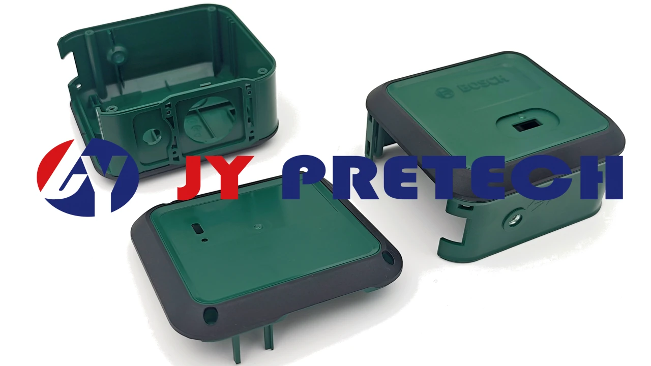
A second hypothetical project might place a soft perimeter around an electronics enclosure. Here the designer must explain the mating surface and closure arrangement, not simply label the soft material as a gasket. The boundary between polymers, the compressed surface and any interruptions around fasteners all influence the function. A visibly complete second shot is only an initial observation; it does not establish the enclosure’s ingress performance.
Define the finished assembly test and who performs it. A part-level dimensional check can support that evaluation, but it cannot replace testing the assembled enclosure under its specified conditions. Our team can review multi-material interfaces and molding feasibility; the acceptance requirement should identify whether the customer needs a grip feature, a retained cushion or a validated seal.
A two-color boundary also has to survive assembly
Some two-shot components use contrasting colors primarily for appearance. Their boundary can still run beside a latch, opening or locating feature. If the second material projects into that area, the housing may need trimming or fail to fit the mating part. Locate the appearance boundary in relation to the functional drawing, including the areas where excess material cannot be accepted.
What the bike-seat case teaches about a two shot injection molding manufacturer
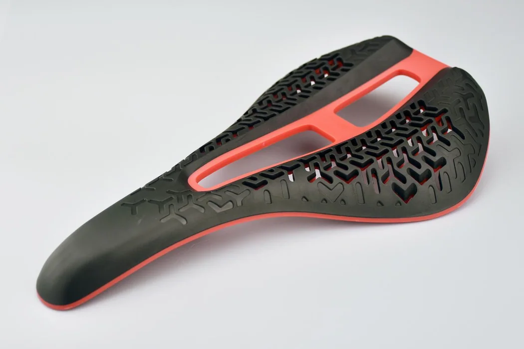
Our bike-seat two-shot case describes a project involving rigid and soft thermoplastic elements within a constrained assembly. The published account identifies limited bonding area, possible delamination and the risk that the second shot could deform the first. It also describes reviewing the assembly and adding contact points through geometric changes.
That is a more useful manufacturing lesson than assuming the original shape can always be molded unchanged. When an interface has little room, material selection alone may not resolve the problem. A revised contact surface or retention feature can change how forces cross the boundary. The design review needs the complete assembly, including nearby features that restrict those changes.
The case does not identify an exact resin pair that should be copied into a new design. Separately, our homepage demonstrates ABS with TPE 60A in a two-shot molding sequence. These are different pieces of project information. The demonstration illustrates an available hard-soft approach; it is not evidence that the bike-seat project used the same materials or that either combination suits every outdoor application.
Choose the polymer pair before committing the joint to steel
JY Pretech lists PA, PBT, PC and PP among its rigid materials for two-shot work. Its elastomer range includes TPE-S, TPE-U, TPE-E, TPE-A and TPE-O families. These names describe a broad manufacturing range, not a universal compatibility matrix. The particular grade, additives and intended application still need review. Our material capabilities provide a starting point for that conversation.
ABS and TPE 60A demonstrate a combination, not an unrestricted specification
The published ABS and TPE 60A example is relevant when discussing a rigid body with a softer surface. However, hardness alone does not specify adhesion, chemical resistance, appearance or processing suitability. Include the exact grade proposal and the component’s exposure conditions. If the buyer requires an approved resin source, make that restriction visible before the tooling concept is finalized.
For general technical background, Avient’s overmolding guide treats material selection, joint design and processing as connected decisions. That supports a grade-specific review; it does not establish that JY Pretech uses a particular Avient product. A proposed substitute should be evaluated against the approved component requirements rather than accepted because it belongs to the same broad polymer family.
For the controller’s soft side panel, keep the proposed color formulation with the material pair used to assess its exposed peeling edge. For the enclosure perimeter, keep it with the pair intended for the sealing boundary. If a later color change is proposed, the team can then identify which interface requirement needs review. A similar-looking soft surface should not inherit an attachment or sealing decision made for a different formulation.
One molding cycle and transferred substrates solve different production problems
Our two-shot service distinguishes 2K molding from regular two-stage overmolding. In the described 2K route, two materials are injected on the same specialized machine and the finished component is ejected after the molding sequence. In the regular route, the first molded substrate is removed and placed into another tool for the second operation. The latter generally involves two tool sets.
For a stable repeat-production housing, integrating the two stages can reduce separate handling and align the sequence around one tooling concept. For a design still changing, the flexibility of a transferred-substrate approach may deserve consideration. The decision depends on the component, development stage and agreed order quantity. It cannot be made from the number of materials alone.
The older two-shot comparison gives specific batch guidance, while our broader manufacturing offering includes selected low-volume and no-minimum options. Ask for the conditions applying to your proposed route. A statement about selected molding services should not be treated as an unconditional commitment for a specialized 2K tool.
Our manufacturing capabilities also include insert molding, rapid and bridge tooling, LSR molding and secondary operations. These alternatives are useful when the design needs metal retention, a silicone component or a separate development phase. A responsible proposal may keep one feature outside the two-shot cycle when integration makes the part harder to validate or service.
Prove the material junction without hiding it behind appearance approval
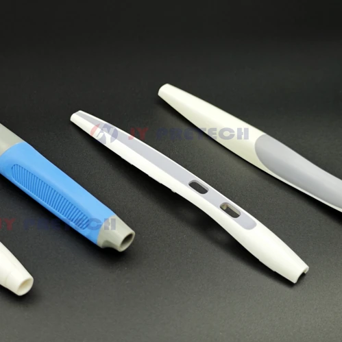
Separate the sample review into the questions that matter to this design. For the hypothetical controller, inspect the grip edge and evaluate attachment under the intended handling. For the enclosure perimeter, assess the molded component against its drawing and evaluate the completed assembly against the agreed sealing method. For a cosmetic housing, compare the visible boundary and the fit of the mating parts.
Do not use one “good bonding” instruction for the controller grip and the enclosure perimeter. For the grip, identify the exposed edge and the handling assessment that would reveal unwanted lifting. For the perimeter, define the completed enclosure’s required sealing evaluation and who performs it. Supply any customer test methods before the trial. The manufacturer should be evaluating two stated interface functions rather than interpreting the same photograph as proof of both.
Record any post-molding work that affects the interface. JY Pretech offers finishing and joining operations such as printing, laser marking, ultrasonic welding and assembly. A grip that works before assembly may be exposed to different handling afterward. The release review should therefore reflect the delivered component condition, including operations that occur after the two materials have been molded.
When arranging delivery of the enclosure samples, identify the soft perimeter that will later meet the mating face. Agree handling that avoids folding that region before its assembly evaluation. The controller grip has a different vulnerability: contact that catches the very edge being assessed for lifting. Show these regions in the sample instructions so the receiving team preserves the interface evidence, rather than treating both objects as interchangeable soft-touch housings.
Release the hard-soft design when the interface decision is complete
A hidden retention feature must leave room for the device inside
Return to the controller example before accepting a new keyway or through-feature. An internal rib, circuit board support or battery compartment may occupy the space that appears available in the external part model. If retention is strengthened by changing that space, provide the mating geometry so the tooling discussion can assess the whole device. The bike-seat account is relevant precisely because its review considered the assembly rather than treating the soft region in isolation.
Also decide which surfaces may show a tooling witness. A retention feature can move a parting line, require another shutoff or change the ejection approach. Those effects should be visible in the DFM discussion. A buyer comparing proposals should be able to tell whether both manufacturers are pricing the same geometry and the same acceptable appearance condition, rather than two different interpretations of an unfinished interface.
A serviceable enclosure may need a separate seal instead of a permanent joint
Integration is attractive when it removes an assembly step, but maintenance can change the answer. If the enclosure opens repeatedly and the sealing element is expected to be replaced independently, permanently joining it to the housing may complicate the service plan. Compare the complete life of the assembly with a separately molded elastomer component before deciding that the fewest pieces must be the best solution.
JY Pretech’s silicone and LSR capabilities provide another manufacturing discussion when a flexible component has different material requirements from the proposed TPE. This is a route comparison, not a claim that silicone and TPE can be exchanged in an existing tool. The material choice changes the manufacturing review and should be resolved with the geometry, expected exposure and assembly method rather than after the first tool has already been ordered.
For either route, retain a sample that represents the accepted component condition. When the buyer later changes a cleaning agent, mating surface or closure force, compare that change with the original interface requirements. A repeat part number should not conceal a new use condition. This makes the initial manufacturing decision useful beyond the first delivery and gives both engineering teams a clear basis for discussing a revision.
A useful manufacturing handoff includes the rigid and soft geometry, exact materials, visible boundary, critical fit features and the intended functional checks. Our CAD-to-sampling process explains how drawings, DFM, tooling and sample review connect. The earlier mold development article adds context for the stages before production.
When reviewing the proposal, ask what would happen if the visible soft edge started to lift or the first shot moved during the second operation. The response should refer to your component’s geometry and material pair. That is where JY Pretech’s coordinated tooling and molding support can be useful: resolving the joint as a manufactured feature before a polished sample makes the design feel finished.