

 Get a Quote
An Insert Molding Manufacturer for Threads, Contacts and Molded Locators
The metal feature often determines whether an industrial plastic assembly can do its job. A thread must accept its fastener, a conductive element must remain correctly positioned and a locator must meet the adjoining part. An insert molding manufacturer needs those functions described before deciding how the insert will be held and surrounded by plastic. JY Pretech’s insert molding capability brings metal inserts and molded material into one component, with location, retention, tolerances and feasibility reviewed against the customer’s drawing. Begin with the metal definition and the assembly interface, as well as the finished plastic shape.
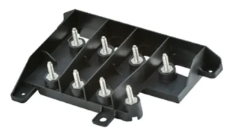
Different metal inserts create different molded-part decisions
An enclosure can combine threaded fastening points, conductive elements and locating details, yet each places a different requirement on the molded carrier. Identify what each metal feature must do and which plastic surfaces establish its position before treating the component as one insert-molding order.
A threaded insert must transmit the fastening load into the plastic
For an equipment enclosure that will be opened repeatedly, the thread is only one part of the connection. The insert’s outside geometry and its position in the surrounding plastic also matter. Tell JY Pretech how the screw enters, what it clamps and which molded features locate the enclosure. The manufacturing review can then consider whether the insert and local wall geometry describe a feasible assembly.
A buyer comparing inserts by thread size alone can overlook a changed outside length, flange or retention feature. Even when the same fastener fits, the replacement may require a different mold location or place material in a different region of the boss. Keep the complete insert drawing under revision control and assess an alternate as a component change.
A conductive insert needs an exposed contact definition
In an electrical component, specify which metal surfaces must remain exposed and which are intended to be encapsulated. The molding tool needs a way to locate and support the element while preventing plastic from reaching an unwanted contact region. A visually neat part is insufficient if the mating contact cannot reach its working face.
Consider a device developer combining a contact and a plastic mounting feature. The team should provide the contact’s orientation, its relationship to the mounting datums and any sensitive surface condition. Electrical performance, insulation requirements and the customer’s applicable acceptance tests must be defined for the actual assembly. Insert molding alone does not establish a product’s electrical rating.
A molded metal locator should be referenced to the mating assembly
A locator can be positioned accurately relative to the outside of a part yet be wrong for the adjoining mechanism. Identify the surfaces that locate the plastic component in use. The metal feature’s permitted position and orientation should be expressed from those references, rather than from an easily measured but functionally unrelated edge.
This is particularly relevant when several inserts share one molded carrier. The relationship between them may control assembly more strongly than each individual feature’s distance from the outer contour. Provide the mating geometry where possible so the proposed inspection can address the actual locating task.
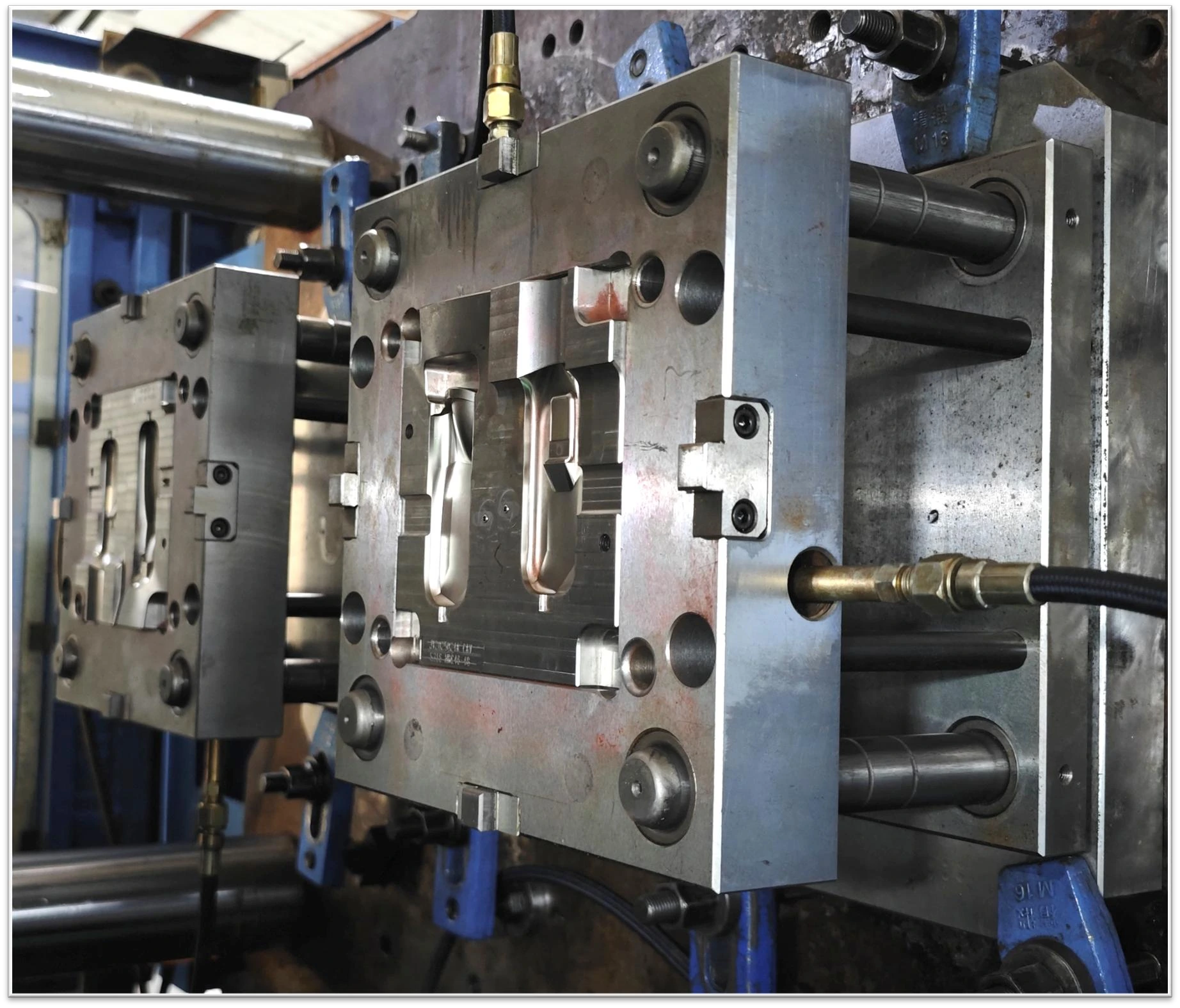
Choose insert molding or later insert installation around access and assembly
JY Pretech lists insert molding together with secondary operations including insert installation, heat staking and ultrasonic welding. These are different manufacturing options, not interchangeable descriptions of one process. In insert molding, the preformed component is present when the plastic is molded around it. A later installation step starts with a molded plastic component and adds the insert through an agreed assembly method.
For general process background, Protolabs describes the preformed insert being loaded before molding. Its own tooling, insert supply and production policies belong to that manufacturer. At JY Pretech, the route, supplied insert and inspection scope are reviewed for the customer’s part.
When molding around the insert deserves review: the design requires an integrated metal/plastic relationship, and the insert can be supported in the proposed tool without losing its functional surfaces.
When later installation deserves review: the molded component can provide suitable installation access, and the selected joining method can meet the assembly requirement.
When neither route should be assumed: the insert drawing, local wall geometry or required acceptance remains unresolved. Those gaps should be closed before the unit-price comparison becomes decisive.
An industrial enclosure with several standard fastening locations may benefit from examining both options. By contrast, a specially shaped conductive element can make location during molding central to the architecture. The choice should follow how the metal must function, how it can be handled and how the final assembly will be verified.
The insert molding manufacturer needs the incoming metal specification
Agree who supplies the inserts and what drawing defines them. JY Pretech’s capability statement does not imply that every insert is stocked or sourced under one standard arrangement. If the customer supplies the metal, provide the quantity needed for trials as well as production and clarify the acceptance of incoming components before the molding schedule is confirmed.
Insert orientation should be unambiguous before the mold closes
A symmetrical-looking insert may contain an orientation-dependent contact face, internal feature or coating. Show the intended direction on the drawing and explain what prevents an incorrect loading condition. The manufacturing team should be able to distinguish a valid insert from a reversed or incompatible one before it becomes part of the molded component.
For a part with multiple metal elements, identify each type and position. A mixed insert set can create errors that are not obvious from the outside after encapsulation. The proposal should address how the insert positions are confirmed, with the actual loading and verification method agreed during the tooling and process review.
Metal surface condition belongs in the encapsulation discussion
If plating, a protective treatment or a sensitive contact surface is specified, make that requirement visible before trial work. It may affect handling, tool contact and the acceptance of the finished assembly. Do not assume that a visually equivalent metal component has the same surface condition, or that a treatment can be changed without assessing the molding and application consequences.
The same care applies to the insert’s dimensional variation. A cavity designed around one nominal metal model must accommodate the agreed incoming specification. If an insert’s tolerance changes, review whether its locating surfaces and the surrounding plastic still have a workable relationship. Otherwise the assembly problem may appear to be a molding inconsistency when the incoming component definition has changed.
Match the surrounding polymer to the insert assembly’s duty
Our published material range includes PC, PA and PBT, among other thermoplastics. These provide material families for discussing housings, structural details and electrical components. The exact grade must be selected against the application, insert geometry and molding review. A listed material family does not establish that every grade is suitable around every metal feature.
PC, PA and PBT should not share an unchanged insert release by assumption
If a customer proposes changing the polymer while keeping the metal and outside dimensions, evaluate that proposal as a technical revision. The material change can affect the local molded geometry and the way the insert assembly responds in use. Review the selected grade’s information and the actual part requirements before treating the old tool and accepted samples as sufficient evidence.
JY Pretech also offers high-performance material molding for PEEK, PPSU and PEI. A temperature or exposure requirement may justify reviewing that route. It should not be selected simply to make an insert assembly sound more robust; the duty, dimensional interfaces and processing feasibility still need to support the choice.
Where an enclosure also needs a soft grip or sealing region, our portfolio includes overmolding and two-shot molding. Keep that material interface separate from the metal insert requirement in the brief. Combining functions may be useful, but each added material introduces another relationship that must be defined and accepted.
Use the mold trial to expose insert position and access problems
Before tool construction, JY Pretech’s DFM and sampling workflow reviews features such as wall thickness, draft, gates and parting lines. For an insert-molded component, connect that review to how the metal is supported and where plastic is allowed to reach. A gate location or tool contact that is acceptable on a hidden plastic wall may be unacceptable at a working contact surface.

Thread access and contact exposure should be checked on the supplied condition
Check that the mating fastener or contact can reach its intended surface after all agreed operations. A drawing measurement can confirm position, while an assembly assessment can answer a different question about access. Define the appropriate method and acceptance for each instead of assuming that a successful visual inspection resolves both.
For a threaded enclosure, a trial assembly should use the intended fastening arrangement and customer-defined conditions. For a conductive part, the exposed metal regions should be checked against their drawing and application requirements. JY Pretech can coordinate agreed component inspection, while the buyer remains responsible for defining the finished equipment’s performance acceptance.
The article from design to production in mold manufacturing explains why the tool and trial stages need to remain connected. An insert issue should be described with its location, insert version and observed condition so the team can decide whether the correction belongs to the insert, the plastic design or the molding arrangement.
An insert supply change can reopen the mold’s locating decision
Suppose purchasing finds another metal component with the same nominal thread and a similar outside form. Before using it in the established mold, compare the features the tool actually locates. A small change in the seating face, end shape or permitted variation can affect how the insert rests before plastic enters the cavity. The correct comparison is with the complete released insert, rather than the thread description on the purchase line.
A mixed insert family needs a drawing for each molded position
On a carrier containing both fastening inserts and conductive elements, identify which metal part belongs in each location. A shared supplier name or similar envelope does not make the pieces interchangeable. Provide the part numbers and orientation with the assembly drawing so the tool review, trial records and production instruction all describe the same combination.
If the customer wants one plastic carrier to accept alternative insert versions, state that objective before tooling. The team can review whether the concept is feasible and what changes or verification would be required. It should not be discovered through trial substitution after one insert arrangement has already been approved.
For a transferred project, request the existing insert specification and the accepted molded assembly reference together. A loose metal sample helps explain the geometry, but it may not describe the tolerance or surface requirement that governed the original production. JY Pretech can assess a new molding proposal more effectively when the customer identifies which existing requirements must be maintained and which may be reconsidered. This keeps a supplier change from becoming an accidental component redesign.
Deliver insert-molded assemblies with their vulnerable features protected
A protruding contact and a recessed thread create different handling concerns. Agree protection for the surfaces that must reach the assembly bench unchanged. If inserts can bend or contact faces can rub during transport, explain those risks when the packing arrangement is discussed. A generic description of industrial packaging does not identify what this component needs.
For mixed part numbers, keep the insert type and molded revision identifiable. A carrier with the wrong metal version may look nearly identical to the approved part after encapsulation. Delivery documents, any requested labeling and the agreed inspection record should refer to the same released assembly definition.
Start the next review with three items: the complete insert drawing, the finished molded model and the mating assembly requirement. Together they let JY Pretech assess a useful manufacturing route and a meaningful trial. The component you are buying is the controlled relationship between metal and plastic, so that relationship should remain visible from tool design to the final receiving check.