

 Get a Quote
A Precision Injection Mold Manufacturer Must Protect the Datum Chain
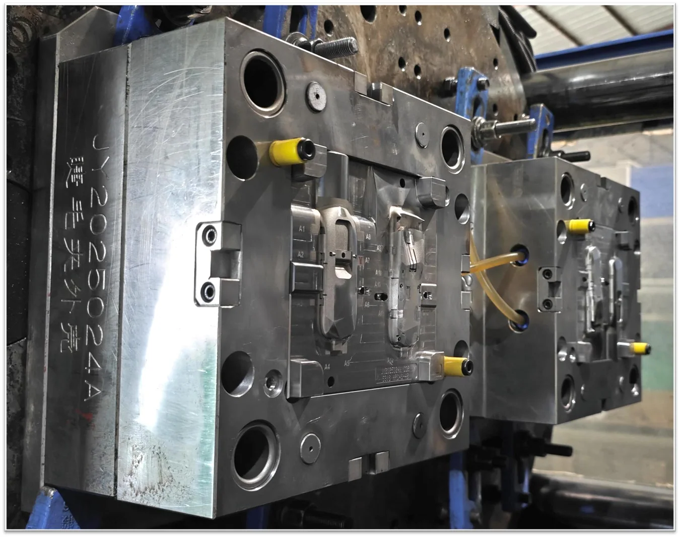
A cover, a base and a connector can each pass an isolated dimension check and still resist assembly. The problem may lie in the relationships between their features. A precision injection mold manufacturer should therefore understand the datum chain: the sequence of references that connects the tool, the molded component and the position that component must occupy in the finished product.
At JY Pretech, moldmaking, molding and dimensional review are connected parts of the service. Engineers evaluating our precision manufacturing approach should begin with the functional interfaces and the agreed measurement condition. Our tool development process provides a route for discussing those requirements before construction. Tight numbers are useful only when they describe the right relationship and can be checked meaningfully.
| Reference in the project | What can be missed | What the buyer should define |
|---|---|---|
| Tool seating surfaces | Correct insert size without correct installed position | How the component locates in the mold assembly |
| Molded part datums | A measurement taken from an irrelevant outside edge | The surfaces that establish functional position |
| Finished assembly | Acceptable individual parts with conflicting interfaces | The mating arrangement and accepted supplied condition |
Precision injection mold manufacturing begins with the mating geometry
A toolmaker needs to know what the component does after ejection. For an instrument cover, that can mean maintaining the relationship between fastener bosses and a viewing opening. For a fluid-handling fitting, it can mean keeping the relevant joint geometry aligned with the mating part. The exterior envelope alone does not tell JY Pretech which relationship controls acceptance.
Housing datums should follow the installed component position
Suppose an industrial buyer specifies the location of a connector opening from a cosmetic perimeter. The cover actually locates in the equipment through bosses on its inner face. If the functional requirement concerns connector access after assembly, the drawing should communicate the relationship to the locating arrangement. Otherwise, an accurate report can answer a question that the assembly never asked.
This does not mean every dimension must be made tighter. It means distinguishing the dimensions that locate the component from those that describe less critical surfaces. Provide the mating definition when it is needed to understand that distinction. Our portfolio includes panels, two-shot housings and clear components, each of which can impose a different relationship between appearance and installation.
Core and cavity interfaces influence the molded relationship
The core and cavity establish opposing portions of the part geometry. Their installed relationship matters alongside the accuracy of an individual machined surface. A buyer discussing a precision tool should ask how its critical features are referenced in the construction and how the resulting part will be evaluated. Specifying one impressive component tolerance does not describe the whole dimensional chain.
JY Pretech’s mold components and export tooling service connects custom tool components with broader mold construction. A replacement insert, a new cavity set and a complete export mold are different delivery objects. For each, identify which interfaces must match existing equipment and which are established within the new supply scope.
A precision mold proposal must account for resin behavior
The tool defines manufacturing geometry; the accepted product is the molded component in its specified condition. Filling, cooling and release can affect that component. JY Pretech’s DFM review covers gating, wall thickness, parting lines, draft and ejection because those decisions influence the result the customer receives. Precision cannot be reduced to a machining claim about the tool steel.
Consider a purchaser replacing a machined development cover with an injection-molded version. The production design retains a broad flat face and several concentrated bosses. The prototype’s fit is useful evidence, but it does not demonstrate how the selected resin will behave in the proposed molding arrangement. The drawing and sample plan should identify the relationships that must survive that change of process.
PC, PPSU and PEEK require a specific material decision
JY Pretech offers engineering plastics and a high-heat material route involving polymers such as PEEK, PPSU and PEI. A PC cover and a PPSU fitting are not interchangeable manufacturing problems. Specify the approved material designation and relevant operating exposure. If the grade is still being selected, identify that uncertainty before fixing the tool and acceptance plan.
A resin supplier’s data can inform material selection, but it should not be substituted for evidence about the finished geometry. Dimensions, surface condition and application behavior depend on more than the family name. Do not infer a guaranteed finished-part tolerance from a general material capability or a single example in the manufacturer’s portfolio.
The Protolabs molding design toolkit is a useful general reference for how geometry and manufacturability interact. Its background principles help buyers ask better questions about walls, draft and release. The actual construction and approval conditions still need to be agreed for the JY Pretech project.
Thin walls and thick bosses should be reviewed as one molded shape
A mounting boss cannot be assessed only as a hole location. Its connection to the surrounding wall, its release arrangement and the local geometry all belong in the manufacturing review. Mark the functional dimension, then allow the design discussion to examine how that requirement can be achieved without creating unnecessary difficulty elsewhere in the part.
If a team revises the wall after a successful first trial, review the effect on the boss relationship rather than assuming that an untouched hole feature is unaffected. The manufacturing record should identify the current whole-part geometry. Isolated feature approvals are difficult to interpret when neighboring geometry changes the part’s behavior.
Separate dimensional conformity from clear-surface acceptance
A transparent cover adds an appearance question that a dimensional report cannot answer. JY Pretech’s portfolio includes clear precision components. The useful purchasing distinction is between a general transparent component, a decorative viewing surface and a part with specified optical performance. One accepted visual sample does not establish every type of optical function.
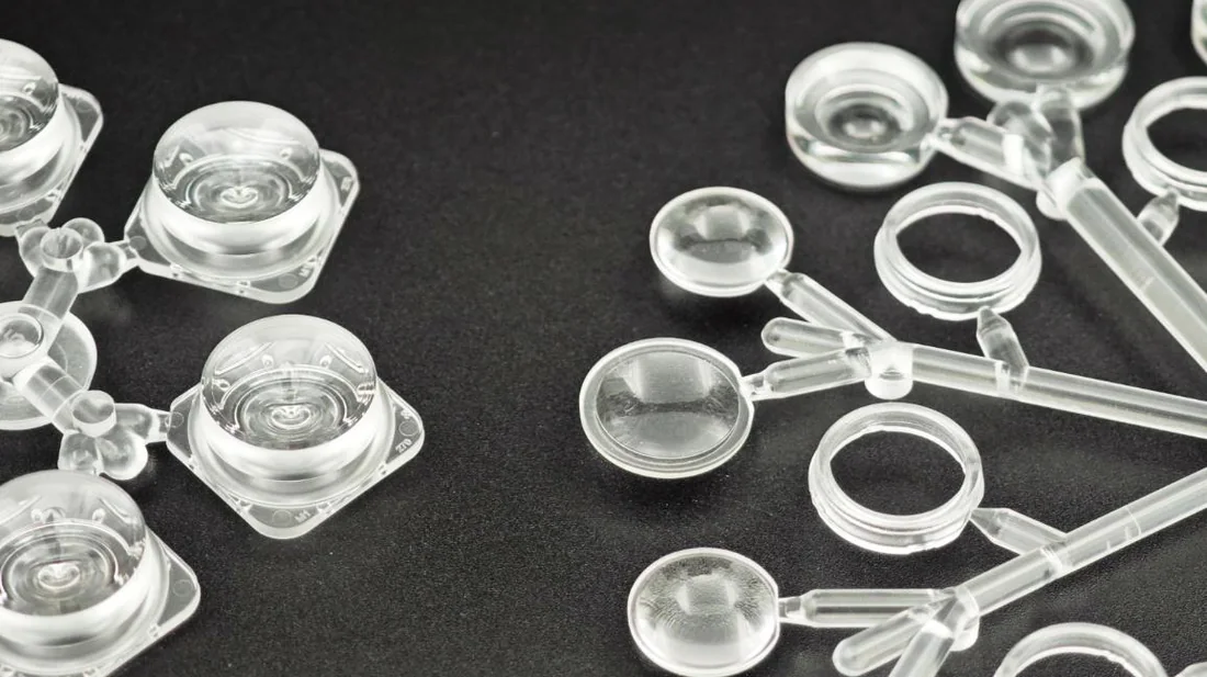
For an industrial instrument, identify the area through which an operator reads the display. A gate vestige or visible mark outside that area may have a different significance from the same feature inside it. Agree the appearance reference and inspection conditions so that approval is repeatable. Avoid asking a toolmaker to interpret an unrestricted instruction such as “perfectly clear everywhere.”
The surface finishing discussion gives additional context for distinguishing tool finish from the finished component’s requirements. Polishing, texture and later decoration can affect different regions. Tie each treatment to the relevant surface instead of applying one vague appearance description to the whole model.
For a clear cover release: identify the locating surfaces, the viewing region and the final supplied condition. Then select the evidence for each. A coordinate measurement, an appearance reference and an assembly evaluation perform different jobs.
Use coordinate measurement to answer the drawing’s actual question
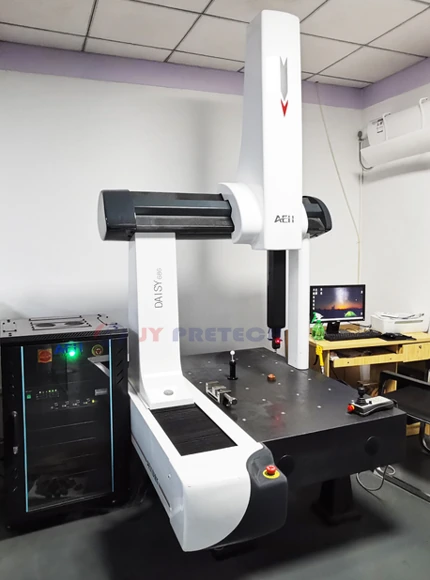
JY Pretech’s company profile identifies 3D coordinate measurement, 2D projection and other inspection resources. That supports a discussion of suitable measurement methods. It does not mean every feature should be inspected with the same equipment or that a coordinate measurement is automatically the best way to judge a flexible or visually critical component.
A molded-part fixture must not hide the fit problem
If a part is held during measurement, its restraint should be understood. A flexible cover forced into a fixture may not represent the condition in which it enters the customer’s assembly. Conversely, a part designed to function under a defined installed constraint may need that condition reflected in the acceptance plan. State the intended condition rather than comparing unexplained numbers.
This is particularly relevant to covers that locate through multiple bosses or that meet a rigid metal panel. Identify the reference arrangement and the dimensional relationships to be reported. If an assembly test is needed, distinguish it from dimensional inspection and define who provides the mating items. This prevents the supplier from being asked to prove fit against an undefined product.
For repeat orders, retain the connection between drawing revision, approved sample and inspection scope. A report should identify the component it describes, not merely list measurements without context. If the material or a critical geometry changes, decide whether the earlier approval remains applicable. The buyer benefits from evidence that can be interpreted after the original project team has moved on.
Projection and coordinate checks should be selected by the feature
A profile visible in a suitable inspection view can present a different measurement task from the position of a bore relative to several locating surfaces. The availability of 2D projection and coordinate measurement gives the project different methods to discuss. Explain the required relationship first; then agree which method, setup and reporting scope are suitable. A measurement method should not be selected simply because its equipment name sounds more advanced.
For a connector opening, the meaningful result may concern position relative to assembly datums. For a parting-line edge, a visual or profile requirement may also be relevant. If a dimension is difficult to establish without cutting or altering the part, identify that issue during planning. The inspection scope must say what evidence is actually obtainable from the supplied geometry and what additional test or fixture would need agreement.
The documented PC connector project provides a useful example of a precisely identified manufacturing configuration: a 1+1 family mold, S136 cavity and core, and PC Lupilon S-3001R. Those details make the reference interpretable. They do not establish a universal dimensional capability. A new connector, even in the same resin family, requires its own geometry, references and acceptance criteria.
If a discrepancy appears between the customer’s measurement and the supplier’s report, compare those definitions before changing steel. Confirm the revision, conditioning or restraint arrangement and the surfaces used to establish position. A difference in setup can require clarification rather than an immediate tool correction. Conversely, an agreed check that exposes a real mismatch should lead to a defined correction and a fresh result tied to the revised state.
Build precision approval around the completed component
Printing, coating, inserts or secondary machining can affect the component delivered for assembly. JY Pretech’s manufacturing capabilities include these associated operations. If a printed reference mark must align with a clear window or a metal insert establishes a fastening interface, include that final condition in the acceptance discussion.
An equipment manufacturer receiving decorated covers should avoid approving only undecorated moldings and assuming the rest is cosmetic detail. Artwork position can affect usability; handling can mark a viewing surface; an insert can change the way a screw loads the part. Identify these dependencies while the sampling and finishing scope can still be coordinated.
Part protection should follow the same geometry. Clear faces should not acquire avoidable marks during handling, while slender projections need an agreed arrangement that protects their shape. Ask JY Pretech to confirm the packing approach for the actual finished parts and destination. Do not infer a fixed packing method from the presence of inspection equipment or from another project’s photographs.
For a development order, our prototype and bridge tooling options can be reviewed around the dimensions and material behavior that need to be established next. A prototype trial can reduce uncertainty. It should not be represented as proof that every future cavity arrangement, resin change or finishing revision has already been validated.
When comparing proposals, ask each supplier to explain how its tool construction, molding trial and inspection evidence connect to the same functional references. That explanation is more useful than a tolerance value detached from the part. A credible precision proposal describes what will be measured, why it matters and which application decisions remain with the buyer.
Put the mating drawing beside the component drawing before the next tool review. Trace the connector position, fastening interface or sealing relationship back through the proposed references. If that chain is clear, JY Pretech can discuss a tool and inspection plan around it. If it breaks at an unnamed surface or an undefined condition, that is the first precision problem to solve.