

 Get a Quote
When a Multi Material Injection Molding Supplier Should Challenge the Stack
Rigid plastic, a soft grip and a metal fastening feature can be combined in several ways. They do not all have to be integrated into one molding sequence. A multi material injection molding supplier should help an engineer decide which interfaces deserve integration and which should remain separate. JY Pretech supports insert molding, overmolding, 2K molding, silicone components and supporting assembly operations. Start with the function of each material in our manufacturing portfolio, then choose the route that keeps the finished assembly practical to manufacture and use.
The most integrated design is not always the simplest project. A permanently joined material can remove an assembly operation but complicate repair, material approval or a later design change. The useful question is not how many processes can be added to the drawing. It is which combination solves the actual product requirements with interfaces that can be specified and assessed.
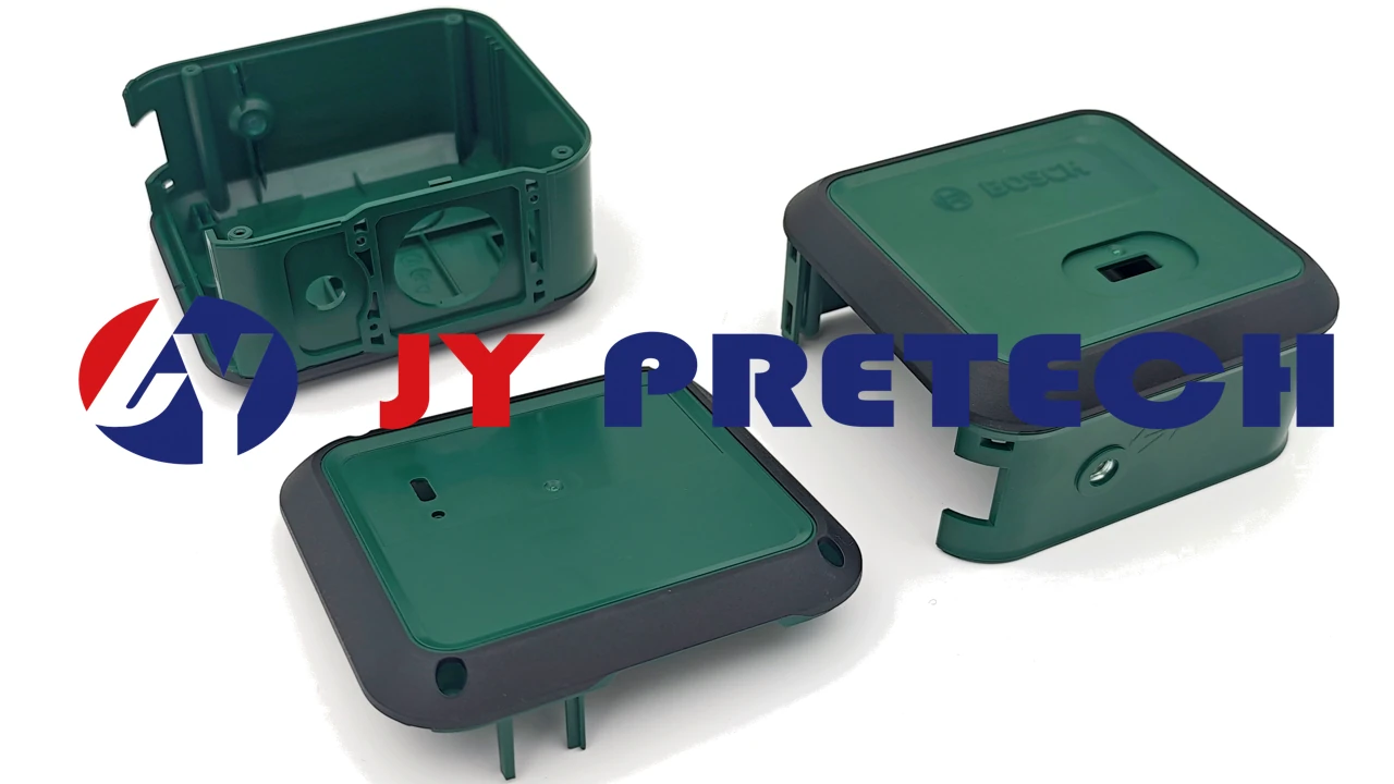
Map the multi-material assembly by function before naming a process
Take a hypothetical portable measuring instrument with a rigid shell, a flexible gripping area and a metal threaded feature. The shell locates internal parts; the grip addresses the hand-contact surface; the threaded feature supports fastening. Each has a different reason to exist. Writing “multi-material molding” across the whole assembly does not tell the manufacturer which relationships are fixed and which can change.
Mark those relationships on the assembly model. Identify whether the metal feature must be present during molding, whether the soft portion needs to be permanently attached and whether the rigid shell must open for service. This gives the engineer reviewing the component permission to question an unnecessary interface without losing the product’s purpose.
A rigid shell should carry the dimensions that locate the instrument
JY Pretech lists PA, PBT, PC and PP for two-shot substrates and offers other rigid polymers within its broader material range. The appropriate grade depends on the component and use conditions. Features that locate a circuit board or connector should be defined in the rigid geometry, with tolerances related to their actual function. The soft surface should not silently become the reference for an assembly feature merely because it is easy to reach with a measuring tool.
If the customer needs a high-performance polymer, our offering includes PEEK, PPSU and PEI. Those routes deserve review when the application requires them. Their availability is not a reason to replace a suitable conventional substrate automatically. Changing the rigid material can alter the tooling and processing discussion as well as the relationship with the second material.
A metal insert and a molded soft region need different retention decisions
Our insert molding capability integrates metal inserts with molded material, while insert installation is also listed among secondary operations. The proposal should say which route is intended. A metal feature positioned in the mold needs a locating and retention concept; a feature installed afterward needs an assembly access and attachment plan. Those distinctions remain important even if both routes produce a similar-looking final component.
For the measuring instrument, show the threaded feature and the surrounding grip together. A retention detail for the elastomer may compete with the space required to locate the metal insert. Reviewing the interfaces independently can miss that conflict. The advantage of coordinated tooling and molding support is the opportunity to resolve it before either feature is treated as fixed.
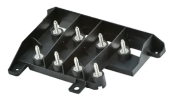
Ask a multi material injection molding supplier which interface can be removed
Before selecting a complex tool, test whether each junction is necessary. Could the soft region end before the service cover? Could the threaded feature be installed after molding without compromising its function? Could an identifying graphic be printed instead of molded as another material? These are practical manufacturing questions, not reasons to dismiss integration altogether.
- Keep an interface integrated when the geometry and product requirement justify a permanent relationship that can be evaluated on the finished component.
- Keep a component separate when replacement, assembly access or independent material qualification is central to its job.
- Change the manufacturing stage when a feature can be installed or finished later with a clearer approval route.
A second hypothetical assembly might need a flexible sealing component that is expected to be replaced during servicing. Permanently molding it to the rigid housing could remove an initial installation step while making replacement impractical. A separate silicone component may deserve comparison. The right answer depends on the material, geometry and maintenance plan; it cannot be inferred simply from the presence of two materials.
JY Pretech’s LSR manufacturing capability provides a route to discussing silicone parts and overmolding. Silicone and thermoplastic elastomers are different manufacturing choices, however. Do not substitute one for the other in an existing drawing without reviewing the required process and component behavior.
Choose the multi-material molding sequence around what must remain fixed
A 2K cycle links both polymer stages to the tool concept
JY Pretech describes 2K molding as two material stages on the same specialized injection molding machine, followed by ejection of the completed component. That approach is relevant to compatible two-material and two-color parts. It connects the stages within a common production arrangement, so the tool needs to manage the first material’s location and the boundary of the next shot.
Our two-shot service includes TPE-S, TPE-U, TPE-E, TPE-A and TPE-O families, alongside the rigid substrate options. This is a range for discussion, not a promise that any pair will adhere. Identify the exact grades and required attachment before treating the combined component as ready for tooling.
A transferred substrate separates the molding stages
Regular overmolding, as distinguished in our service description, removes the first molded substrate and places it in another tool for the second operation. This generally uses two tool sets. It creates a handoff between stages that needs a defined substrate condition and locating method. It may be a useful route when the design or production arrangement benefits from that separation.
For the instrument’s development order, rapid or bridge tooling can be discussed around the specific unresolved layer. The team might need to assess the rigid shell with its metal insert before committing the final grip boundary. State whether a proposed sample includes that boundary or only establishes space and access around the insert. Evidence for the metal-to-shell relationship should not silently become approval of a soft layer that the sample never reproduced.
A joining operation can be preferable to molding every element together
JY Pretech lists ultrasonic welding, heat staking and assembly within its supporting operations. These can form part of a manufacturing proposal when separate molded components offer a more practical path. The proposed joining operation still needs to be assessed for the particular geometry and materials. Its presence in the portfolio does not qualify every mixed-material assembly automatically.
Compare the delivered condition rather than counting molded pieces alone. A two-piece housing that can be sampled, inspected and serviced clearly may be preferable to a highly integrated component that obscures its critical interfaces. Conversely, a well-defined integrated component can remove unnecessary handling. The engineering review should explain why the proposed route serves this assembly.
Do not confuse mechanical attachment with a sealed material boundary
The published bike-seat case describes limited bonding area and the addition of contact points after an assembly review. It illustrates why interface geometry deserves attention. It does not establish that a mechanical retention feature in a new product will create a sealed junction or meet a particular durability requirement.
For general background, Avient’s overmolding guide discusses material selection and mechanical interlocks as parts of the design process. The buyer should separately identify whether the new joint must remain attached, prevent leakage or provide a comfortable surface. Each requirement needs an appropriate assessment of the actual component.
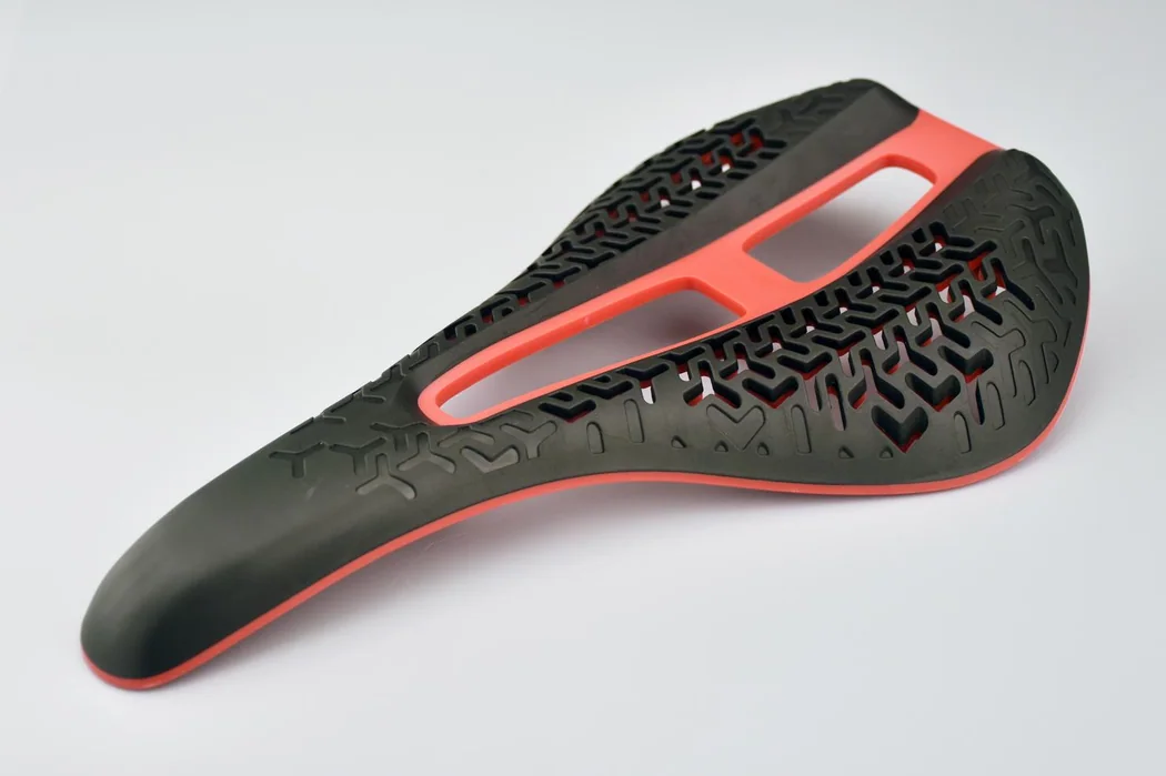
If the portable instrument is expected to resist a liquid environment, define the assembled product’s evaluation rather than assuming that a continuous-looking overmold proves the requirement. If only the grip’s attachment matters, specify that directly. A supplier can then review the interface against the correct question instead of trying to interpret a broad instruction such as “waterproof soft material.”
Prepare one coordinated drawing package for the material stack
Show the rigid shell, metal feature and grip as identifiable elements in the instrument assembly, alongside their dimensioned requirements. Mark the insert axis and the soft boundary where the proposed layers compete for space. JY Pretech requests STEP or IGS geometry with material, quantity, finish and critical requirements; our project process connects those files to quotation, DFM and sampling. The assembly view should make the three-material relationship visible rather than ask the reviewer to reconstruct it from isolated drawings.
For the instrument’s metal feature, include the insert specification and whether it is customer supplied. For the rigid shell, identify locating dimensions and the mating geometry. For the grip, identify the approved material region, exposed edges and any required attachment assessment. Keep these instructions coordinated so a revision in one part does not invalidate another sheet unnoticed.
Make finishing scope equally clear. A printed legend near the soft region, a laser-marked identity and a post-installed insert are different operations. Identify which are included in the supplied component and which occur at the customer’s plant. This lets the sample review examine the component at the correct stage rather than approve an unfinished version under the final assembly part number.
Release the assembly route only after the mixed-material sample answers its own questions
A threaded attachment should be assessed without borrowing support from the grip
For the portable instrument, identify what holds the threaded feature in its intended position when the grip is absent from the reasoning. If the rigid shell and metal feature cannot perform the required fastening job without relying on an unspecified soft layer, the design needs clarification. The elastomer may contribute to the assembly, but that contribution should be deliberate and evaluated rather than discovered after a fastener moves in the first samples.
Likewise, ask whether tightening the fastener changes the soft surface nearby. A proposed retention feature or assembly tool may occupy the same small region as the overmold edge. Reviewing the fastening operation with the mixed-material sample can reveal this conflict before the separate features are accepted independently. The resulting correction might belong to the insert route, rigid support or grip boundary; the complete model allows the manufacturer and customer to choose between those options.
If the insert specification changes later, revisit that combined relationship instead of treating the metal feature as an interchangeable purchasing item. Its geometry and location are part of this instrument’s material stack.
At the sample stage, review the metal insert’s relationship to the housing, the rigid component’s fit and the grip boundary as separate findings. Then check them together in the intended assembly. If a correction to the soft feature requires a rigid wall change, reassess the neighboring fastening arrangement. This is where the original functional map becomes useful again: it shows which product relationships the correction must preserve.
For the mixed-material instrument part, identify whether the metal feature is already fitted when the grip samples arrive. A protruding metal end could meet an adjacent soft region if the proposed pack lets components touch. Review that contact with the actual assembled geometry, and distinguish deliveries of separate inserts, rigid shells and completed hard-soft parts. The receiving team needs to know which layers are already present before using the shipment to evaluate the chosen assembly route.
A better material stack is often the one with the clearest responsibilities. Give JY Pretech permission to question the grip boundary, insert route or joining stage while those choices are still open. The earlier article on tooling and molding responsibilities can help frame the discussion. Keep each material because it earns its place in the instrument, and choose its manufacturing interface with the same care.