

 Get a Quote
A Custom Silicone Parts Supplier for a Product Family With Different Loads
A product family can contain three white flexible components that belong on three different engineering drawings: a seal compressed inside a housing, a removable protective cover, and a soft interface that touches the user. Buying them as one interchangeable “silicone” requirement can obscure the differences that determine whether they work. A custom silicone parts supplier should first establish the load, mating geometry and supplied condition of each component, then select a manufacturing route.
At JY Pretech, liquid silicone rubber injection molding and compression molding provide two routes to discuss. Our wider capabilities also include rigid plastic molding, two-shot molding and finishing. That combination is useful when the flexible part belongs to a larger assembly. It does not make one compound or one process suitable for every member of the family.
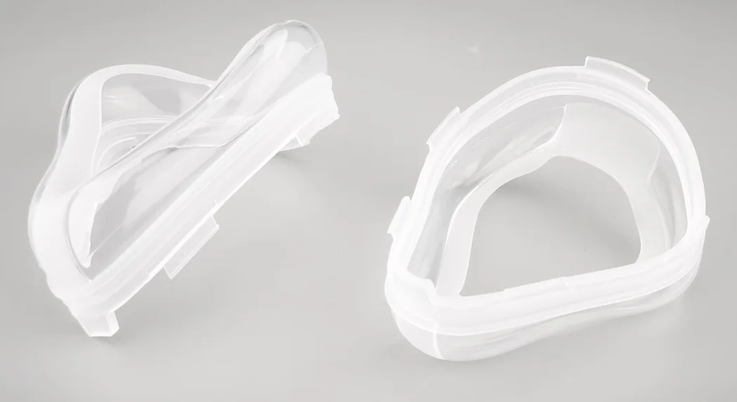
A custom silicone parts supplier should separate the seal from the protective cover
Consider an equipment team developing a handheld enclosure with a perimeter seal and an external protective boot. The seal must fit its groove and compress against the mating housing. The boot must stretch over the outside features without losing its intended position. Even if both parts have similar color and a similar feel, their critical dimensions, handling risks and approval methods differ.
Our LSR service describes sealing, protection and shock-absorption applications in electronic products. Those are useful starting functions, not finished performance ratings. Give the engineering team the housing geometry and the service conditions so that the component can be assessed as a working interface. A photograph of a successful cover cannot establish the sealing behavior of a new perimeter gasket.
Compression in a housing groove needs a defined assembled position
For the seal, show the closed housing position and the regions that contact the silicone. Identify the surfaces that must remain free of a gate witness, a trimming irregularity or an unwanted parting-line feature. The supplier then has something specific to review during mold design. Simply asking for a “smooth seal” leaves the important location unresolved.
Specify how the sample will be checked: freely resting, seated in its groove, or compressed in an agreed assembly fixture. A flexible profile can assume different shapes under those conditions. Dimensioning the unstressed part and accepting it under compression are separate decisions; connect both to the drawing rather than letting the receiving team invent a method later.
A removable silicone boot needs installation access as well as flexibility
For the protective boot, supply the enclosure’s projections, openings and installation direction. A locally thin region may stretch around a feature during assembly, while a thicker surrounding area controls the final position. The review should follow that movement. It is not enough to inspect the cover lying flat and conclude that it will install without damage.
If the boot is intended to be removed for service, assess removal with the same attention. An integrated overmold may reduce loose components but change the replacement method. Our hard-soft and two-shot molding capabilities offer a related route for appropriate material pairs. A serviceable, separate silicone component can still be the better architecture when the user must replace it independently.
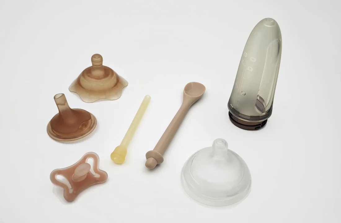
Choose liquid silicone injection or compression molding around the component geometry
LSR injection molding introduces a liquid silicone formulation into a mold and cures it into the flexible component. Our published sequence covers tool creation, material preparation, injection, curing, demolding and secondary operations. Compression molding places a prepared charge into the tool and forms the part by closing the mold under pressure. Both routes require a defined compound and a tool suited to the shape.
For a family with fine flexible features, repeated details or a geometry that benefits from controlled injection, LSR deserves an early review. A simpler silicone form may justify a compression discussion. Avoid deciding from the process name alone: cavity arrangement, trimming access, material choice and planned order quantities can change the comparison.
A compression-molded edge needs a realistic trimming requirement
Our compression process description includes charge preparation, mold closing, part release and removal of flash. For a protective pad with a noncritical outer edge, the permissible trimmed boundary may be relatively straightforward to define. For a sealing lip, that same boundary can become a functional surface. Mark the difference before the tool is designed.
A buyer should therefore compare supplied parts after the agreed trimming operation. A quotation that assumes an ordinary peripheral trim and another that includes a more demanding edge requirement describe different work. Discuss the actual edge and its acceptance reference with JY Pretech instead of treating all hand-finishing as an identical commercial allowance.

Fine LSR details should be reviewed together with demolding
A narrow flexible projection may appear easy to release because silicone bends. That flexibility does not remove the need to review the projection’s shape, surrounding support and handling during removal. Ask how the actual feature will be exposed and protected through the molding sequence. The answer should relate to the drawing, not a general statement about silicone elasticity.
The same reasoning applies to a thin membrane adjacent to a thicker frame. Identify where the membrane is intended to deform and where its position must remain controlled. When samples arrive, check the membrane in the intended mounting arrangement. That can expose a functional conflict that is difficult to recognize from an unsupported part on a measurement bench.
Keep silicone compound identities distinct across the product range
Our material references include WACKER ELASTOSIL LR 3003, SILASTIC LSR families and Shin-Etsu KE G2000, among other silicone options. These names identify material families to discuss. They do not establish that every listed formulation is available for a particular order, has identical behavior or carries the same documentation. Record the exact proposed grade and color system for each released component.
WACKER’s silicone product overview illustrates why a complete grade designation matters: its LR 3003 entries distinguish several hardness variants. Use the producer’s current technical document for the selected grade. Do not transfer properties from one suffix or hardness variant into another material order.
Hardness alone does not define the installed silicone response
A thin lip and a thick pad made from the same compound do not offer the same resistance to movement. Their geometry and restraint differ. Record hardness where it matters, but also define the assembly displacement, contact region and conditions used to evaluate the sample. Otherwise, a purchasing specification can be numerically clear while the actual product expectation remains vague.
A silicone color match should not silently authorize a compound change
If the silicone product family shares a visible color, keep that requirement separate from material approval. A reference sample can control appearance without authorizing a different silicone grade. When a proposed pigment or compound changes, review its relevance to the part’s duty and any required documentation before accepting the substitution.
For a hypothetical distributor supplying spare protective covers in several colors, that distinction also improves identification. Link each color and part number to the accepted grade and drawing. A box labeled only by appearance makes it harder to distinguish a deliberate variant from an unintended substitution when the next order reaches the service department.
Coordinate the silicone component with the rigid plastic it actually meets
JY Pretech’s manufacturing capabilities include injection-molded rigid parts, insert molding and secondary assembly support. For a silicone seal seated against a molded housing, that wider view helps put both sides of the interface into the engineering discussion. The seal drawing should not be developed in isolation from the plastic features that locate and compress it.
The rigid housing may use PC, ABS or another specified resin from our material range. Its wall geometry, bosses and mating surfaces still need their own review. Changing the rigid material or moving a fastening point can alter the space available for the silicone even when the flexible part number remains unchanged.
Use a trial assembly to decide which component needs correction. If a seal appears loose, compare the molded groove, the silicone profile and their accepted drawings before modifying either tool. Tightening the silicone dimension to compensate for an unapproved housing variation can create a second problem when the housing is later corrected.
For teams still refining that rigid component, our discussion of custom plastic parts through design changes explains how geometry and material revisions affect development supply. Apply that same version discipline to the silicone interface so that the approved pair can be reproduced.
A silicone lip and a rigid groove should have one change owner
Imagine that the enclosure team widens the groove to simplify assembly while the purchasing team simultaneously asks for a firmer silicone sample. Either change may be reasonable on its own. Together they can obscure which adjustment produced the observed improvement. Keep the trial versions identifiable and ask for one deliberate change at a time where the development schedule allows it. The retained sample should represent the final pair, rather than whichever loose component happened to be approved first.
For repeated builds, include the mating drawing reference with the silicone release. This is especially valuable when several enclosure variants share a similar outline but differ around a port or fastening feature. A cover that stretches over both versions may still seat correctly on only one. Variant identification therefore belongs beside dimensions and compound identity, rather than being left to a color label applied after molding.
Approve the silicone family as separate, identifiable supplied components
Our published project process asks for drawings, material, quantity, finish, timing and delivery requirements. For a silicone family, add a component matrix showing which parts are loose, which are assembled and which require distinct sample approval. The quantity of complete devices does not automatically equal the order quantity of every flexible component.
Define packaging around the vulnerable feature. A thin sealing lip should arrive in a condition that allows the receiving team to assess its released geometry. A protective boot should remain identifiable by version and color. Confirm the arrangement for the actual order; a particular tray, bag or protective insert should only be treated as included when it has been agreed.
A receiving trial can make that requirement concrete without inventing a universal packaging specification. Open the proposed pack, identify a part, remove it by the intended method and place it into the relevant assembly. If the flexible edge becomes difficult to separate from adjacent parts, or several similar variants can no longer be distinguished, revise the handling arrangement before the full release. The object is a component that can reach the next operation in its accepted condition, not an elaborate package for its own sake.
Set the order schedule after the manufacturing route and sample sequence are clear. A family containing both compression-molded and injection-molded silicone may have separate tooling or approval steps. Do not assume that approving the simplest pad releases the more intricate seal. The project quotation and agreed milestones should identify which component is ready for production and which still needs an engineering decision.
Where the application involves medical use, bring the documentation and downstream processing requirements into the project at the beginning. A silicone family name does not establish suitability for patient contact, a sterilization method or sterile delivery. Those decisions need the selected material evidence and the device team’s defined acceptance responsibilities.
The most useful first release may be a seal-and-housing assembly trial alongside separate boot samples. That lets the team test two different questions without forcing one approval method onto both components. Once each silicone part has its own grade, drawing and supplied condition, the product family becomes easier to purchase repeatedly and easier to change deliberately.