

 Get a Quote
Injection Mold Components Supplier for a Replacement That Actually Fits
A worn insert arrives on the purchasing desk with a photograph and an instruction to make another one. Its polished face is scratched, its original drawing is missing and nobody is certain which of two similar tools it came from. An injection mold components supplier needs a better definition than the visible outline if the replacement is expected to restore the approved molding configuration.
JY Pretech supplies custom tooling and mold components alongside moldmaking and molding services. Begin with our tooling and components capability, then provide the component drawing, tool identifier, material requirement and installed references that are available. For a replacement, the first decision is whether the task is to reproduce an approved design, recover missing design information or deliberately revise a feature. Those are different engineering scopes.
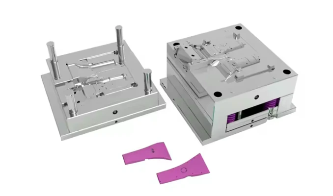
Injection mold component supply starts with identifying the correct tool
A component that resembles another insert may still belong to a different revision or cavity position. Before requesting manufacture, identify the mold, the molded part and the component’s installed location. If a plant maintains several related products, a photograph can help with recognition but should not become the only manufacturing instruction.
Cavity position and orientation should travel with the replacement drawing
For a tool with more than one cavity, record which position the replacement serves. Include orientation and the locating surfaces needed to interpret the drawing. A seemingly symmetric component can contain an asymmetric feature or connection that matters after installation. That relationship should be visible in the supplied definition rather than left for the receiving technician to discover.
JY Pretech’s manufacturing process works from customer files and agreed requirements. STEP or IGS geometry and a dimensioned drawing provide a stronger starting point than an isolated sample. If only a physical item exists, identify that limitation and agree the additional review needed before treating its measured shape as an approved replacement design.
A worn core is evidence of its present condition, not automatically its original size
Wear, damage or a previous repair can change the item being copied. A buyer should distinguish the surfaces that remain reliable references from those that caused the replacement request. Reproducing a damaged edge accurately can preserve the very problem the order is intended to resolve. The required target is the agreed functional geometry, not an unexplained scan of the current object.
Suppose a maintenance team replaces an insert after flash appears at a local interface. The purchasing brief should identify the observed issue and the original definition if available. It should not assume that every dimension on the removed component remains correct. JY Pretech can review the manufacturing scope around the available information without promising that an unidentified sample reveals every original design decision.

A custom injection mold components supplier needs both the part and its interfaces
A cavity insert does not function alone. Its seating surfaces, locating arrangement, neighboring components and molded profile interact inside the tool. State which relationships must be retained and whether the existing tool will remain unchanged. A proposal to manufacture a component is different from a proposal to modify the surrounding mold.
Seat dimensions and molded profiles require separate acceptance decisions
The outside seating geometry determines how the item locates in the mold. The cavity or core profile helps establish the plastic part. Both can be critical, but they answer different questions. Identify the drawing references for each and the evidence needed to accept them. A correct molded profile cannot compensate for an insert that does not seat as intended.
For an equipment housing mold, a replacement that changes the installed position of a local core can move a boss or opening relative to the rest of the component. That is why an isolated size check may be insufficient. Our discussion of precision tooling and datum relationships explains the wider dimensional chain from tool construction to assembled product.
Cooling features must match the existing mold arrangement
If the replacement contains cooling features or interfaces with existing connections, include their location and identification in the review. A surface drawing that omits those relationships can leave the receiving team with a component that appears correct but does not match the installed arrangement. Confirm what must be preserved and what, if anything, is being changed.
Do not infer an improved cycle or a particular thermal result merely because a new component includes cooling geometry. Any change to that arrangement needs a project-specific engineering discussion. The component order should identify the agreed geometry and acceptance scope; an application or production-performance claim needs its own evidence.
Replacing one cavity component should not silently redefine its mating half
A new component may meet its drawing while the neighboring retained component has worn or been modified. Identify whether the order assumes the mating half still represents the approved design. If that assumption is uncertain, bring the interface into the review before manufacture. The supplier cannot establish the condition of an unseen installed surface from the replacement drawing alone.
For a local shutoff or joint between inserts, distinguish restoring the original geometry from matching the existing altered condition. Either task requires a defined engineering decision. Simply reproducing a nominal dimension without explaining the retained interface can leave the maintenance team with an unresolved fit question after delivery.
If paired components are being replaced, identify them as a coordinated set and state which relationships will be checked together. If only one is being supplied, define what the receiving plant will assess during installation. These distinctions help JY Pretech review a realistic component scope and help the buyer compare quotations that might otherwise include different amounts of interface work.
Keep any accepted adaptation in the controlled record. A technician’s successful local adjustment should not become invisible to the next manufacturing order. Updating the relevant component definition preserves the practical knowledge gained during replacement and reduces dependence on identifying the right person who remembers an earlier repair.
Distinguish catalog replacements from custom machined mold components
JY Pretech’s tooling information identifies standards and component conventions including LKM, DME, HASCO, MISUMI and MEUSBURGER. For a catalog item, provide the exact reference and the information needed to verify the version and dimensions. For a custom component, provide the approved drawing. A brand family or a broad category name is not a complete specification.
The DME component range separates alignment, cavity/core, cooling, ejection and other mold elements. That is useful background for organizing a replacement request. It should not be read as a claim that every DME item is stocked or included in JY Pretech’s custom supply. The quotation should identify the actual manufactured or sourced delivery object.
If the purchase request says only “same as sample”: add the tool identity, revision, installed position and the reason for replacement. These facts help distinguish a faithful replacement from an undocumented design change.
Metric and inch references need verification before substitution
A plant with mixed tooling can hold visually similar components from different systems. Check the actual dimensions, threads and interfaces rather than relying on appearance. If an alternative component is proposed, review it against the installed requirement. “Equivalent” should describe an agreed technical relationship, not a shortcut around missing component information.
For a custom part, use one coherent dimensioning convention and make any mixed-system interfaces explicit. This reduces the chance that a receiving engineer must reinterpret a nominal value or guess which reference controls. It also makes the supplier’s inspection result easier to compare with the plant’s incoming review.
Material, hardness and finish define more than the component outline
The export tooling service lists steels including H13, S136, NAK80, 1.2343, 1.2344 and P20. That range supports a material discussion; it does not make those steels interchangeable for a replacement. Identify the original requirement, the intended condition and any agreed heat treatment. If the original record is uncertain, resolve that uncertainty rather than selecting a familiar steel name by default.
S136 and H13 should be specified with the required supplied condition
A material designation alone does not identify every property of the finished component. State the required condition and the evidence expected with the order. JY Pretech’s inspection resources include hardness measurement, but a hardness value must be tied to an agreed requirement and location. The equipment name cannot establish whether the chosen condition suits the tool’s service.
If an existing insert has been repaired or treated after its original manufacture, tell the supplier. The present surface and material condition may no longer represent the original drawing. This can affect how the replacement request is interpreted. A clear brief separates known records, observed conditions and the new requirement the buyer is approving.
Polished and textured cavity regions should retain their own references
A replacement cavity region can affect the appearance of the molded product. JY Pretech’s tooling information includes polished, high-gloss and VDI or Mold-Tech finish routes. Define the surface reference and its boundaries on the replacement drawing. A general request to “match the old tool” is difficult to evaluate if the old surface is worn or damaged.
For a visible enclosure, compare the requirement with the accepted molded appearance, not only the metal surface. Our injection molding finish article gives additional context for discussing the difference. A change in one cavity region should be reviewed against the component it produces and the surrounding appearance that remains unchanged.
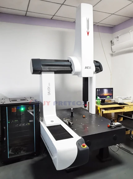
Inspect the replacement against a definition the receiving team can use
JY Pretech’s inspection approach and company profile identify coordinate measurement, projection and other measurement resources. Select the method around the actual feature. The drawing should show the references and dimensions that matter to installation and function, so a report can be interpreted rather than merely filed.
For a locating surface, dimensional evidence may be the relevant starting point. For a textured cavity face, an agreed appearance reference may also matter. For an interface that depends on the existing mold, the buyer may need an installation or trial evaluation. State these different decisions rather than expecting a single inspection method to answer every question.
If the original tool cannot be made available, identify that limitation before manufacture. The order can define what the supplier will verify from the drawing and what the receiving plant will verify after installation. That boundary is more useful than an unsupported promise that a component made from incomplete information will fit every aspect of the existing assembly.
A trial after replacement should remain tied to the current molded-part revision
The plant may have changed the plastic component since the mold was first built. Confirm that the replacement drawing and the current molded-part definition agree. A perfectly reproduced obsolete insert can be the wrong delivery. This is particularly important where earlier modifications were recorded as local notes rather than incorporated into the controlled tool documentation.
After installation, evaluate the features affected by the replacement against the agreed acceptance plan. Do not assume that an unchanged tool identifier proves an unchanged molded configuration. Keep the component identification and any accepted change connected to the mold record, so the next replacement does not begin with the same uncertainty.
Keep mold insert identification ready for the next replacement
Confirm identification and protection for the supplied item. A polished cavity face and a locating edge need handling appropriate to their function. If several similar components are shipped together, distinguish their positions and revisions. Agree the packing arrangement for those actual objects rather than assuming that one method protects every mold component equally.
For a program expected to need repeat custom components, retain the approved files, material condition and inspection scope. JY Pretech’s integrated tooling and component work provides a route for discussing the relationship with the wider molding program. Any spare quantity, delivery schedule or ongoing supply arrangement should still be confirmed for the order.
The worn insert on the desk is therefore a starting piece of evidence, not a complete specification. Give JY Pretech the tool identity, current component definition and the interfaces that must remain unchanged. A replacement becomes a dependable purchasing object when its design target can be distinguished from the wear, damage and undocumented changes that prompted the request.