

 Get a Quote
Silicone Overmolding Manufacturer Decisions at the Rigid-Flexible Boundary
The silicone portion can look perfect while the assembly still separates at its edge. For a rigid carrier with an integrated flexible interface, the first manufacturing question is how those two materials will stay together during use. A silicone overmolding manufacturer needs the exact substrate and silicone grades, the retention geometry and the intended load before treating the joint as a production-ready design.
JY Pretech’s LSR injection molding service includes silicone overmolding as a route for integrated components. Our portfolio also shows a PC and LSR mask assembly. It provides a concrete example of a rigid-flexible construction to discuss, while a new product still requires its own material and tooling assessment. Begin there when your project needs an integrated silicone contact region, rather than assuming any soft material will bond to any rigid plastic.
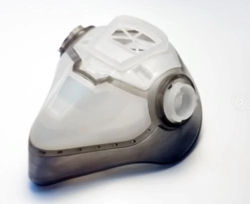
The silicone overmolding manufacturer must define what retains the flexible region
An interface may rely on material adhesion, mechanical capture or a deliberately designed combination. These mechanisms are not interchangeable. A surrounding groove may locate silicone without preventing an edge from peeling. A hole or undercut may provide capture but also change how the tool fills, opens or releases the assembly. The drawing should make the intended retention mechanism understandable.
In a hypothetical device project, an engineer may want a soft perimeter around a rigid PC carrier to remain permanently attached. Another team may need a similar-looking silicone piece to come off for replacement. Those requirements lead to different design choices. Resolve the service expectation before asking the toolmaker to eliminate every separable joint.
A PC carrier needs its full material designation before silicone is selected
PC identifies a polymer family, not every detail relevant to molding and adhesion. Record the specific rigid grade, its color and the surface condition presented to the silicone process. If the substrate arrives from another manufacturing step, describe that step as well. A nominally unchanged carrier can present a different interface after a material or surface-treatment change.
Our material capabilities include PC and other engineering thermoplastics. That range supports a material discussion; it should not be read as a compatibility chart for every silicone formulation. The proposed pair needs evidence from the material producers and an appropriate trial on the actual part. Do not substitute a resin because it produces a similar-looking rigid sample.
Mechanical capture of silicone should resist the expected peel direction
Show how a user can pull, flex or catch the silicone edge. A retention feature that resists a direct pull may experience a different load when an exposed lip is lifted from one end. Include the accessible edges and expected handling in the design review. The purpose is to test the likely separation path, not merely to demonstrate that the materials touch.
If the joint should be inseparable during ordinary service, define what an unacceptable separation looks like. It might be an exposed gap, a lifted edge or movement that prevents the assembly from seating. Those observations can guide sample evaluation. A statement such as “strong bond required” is less useful because it does not describe where the weakness would become a product problem.

Silicone overmolding tool design should protect both the carrier and the sealing surface
The rigid component must be located during the silicone operation. Its position influences the flexible layer’s thickness, exposed boundary and relationship to assembly features. Discuss the surfaces available for support and the regions the tool must avoid marking. A carrier designed only for its own molding operation may need further thought before it can serve reliably in an overmolding tool.
JY Pretech’s project workflow includes manufacturability review before tooling, with wall thickness, draft, gates and parting lines among the relevant features. In a silicone assembly, extend that discussion to the carrier’s location and the shutoff around the overmolded region. These are part-specific questions that should be resolved from the supplied geometry.
A thin silicone edge needs a deliberate shutoff location
The line where silicone is intended to stop should be shown relative to the rigid component. If that line falls near a sealing region, an unwanted protrusion can have a different consequence from a small witness on a hidden surface. Mark functional and appearance zones separately. It helps the toolmaker understand why a seemingly minor boundary deserves attention.
Do not request removal of every visible witness without considering the geometry. Agree on permissible locations and acceptance references during development. Moving an interface after tooling has started can affect support, filling and access to the part. A clearly released boundary is more useful than a late request to make the transition “cleaner” everywhere.
PC carrier support must preserve the plastic features used in the final assembly
A rigid frame may contain locating pins, fastening bosses or openings needed later in the device. Include these in the overmolding review, even when they sit outside the silicone region. The tool should be considered as part of the complete manufacturing sequence, not simply as a cavity surrounding a flexible seal.
If a carrier is supplied externally, establish the incoming condition and acceptance method. A component that meets only an overall outline requirement may still vary at the surfaces used to locate it. Before modifying the silicone cavity to compensate, check the carrier against its released definition. Otherwise, the overmolding operation can become an unintended correction step for upstream variation.
Separate silicone processing from the device’s later exposure conditions
Our LSR material references include WACKER ELASTOSIL LR 3003, SILASTIC LSR options and Shin-Etsu KE G2000. The complete proposed grade should be selected for the project, with the producer’s current processing and application information. A family name alone cannot define the cure behavior, final properties or documentation of the compound that will actually be supplied.
WACKER’s silicone product overview provides producer-level context for different formulations. Obtain the current technical information for the exact proposed grade during selection. That material information and JY Pretech’s qualification of a new assembly answer different questions. Keep the producer’s evidence and the project’s finished-part evidence connected without treating them as the same document.
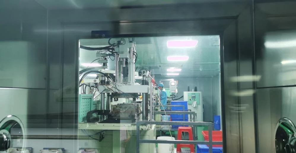
Cleaning chemistry should be assessed at the PC-silicone interface
A hypothetical equipment team may wipe the finished assembly repeatedly while gripping the silicone edge. The engineering question then includes the cleaning agent, exposure conditions and mechanical action at the joint. Asking only whether “silicone resists chemicals” ignores the rigid material and the interface between them. Describe the actual cleaning procedure to the material and device teams.
The same discipline applies to temperature. A silicone compound’s stated behavior does not automatically establish the working limit of the PC carrier or the assembled joint. Distinguish conditions encountered during manufacturing from those encountered during service. The proposed process must be compatible with the carrier, and the finished assembly must be assessed for the duty it will experience.
Use TPE overmolding as a separate comparison when the application allows it
A soft-touch grip and a silicone sealing interface may feel related to a buyer, but they need not use the same material system. Our two-shot molding service includes hard-soft thermoplastic combinations, with an ABS plus TPE 60A example in the published portfolio. That is a distinct option to evaluate when the application’s requirements permit it.
For a handled enclosure whose main requirement is grip and appearance, a thermoplastic elastomer route may deserve comparison with silicone. For an application whose selected silicone formulation and documentation are essential, a TPE sample should not be accepted merely because it feels similarly soft. State what the flexible region must accomplish before comparing the manufacturing architectures.
Avient’s overmolding guidance reinforces the importance of material pairing and process conditions in thermoplastic overmolding. Its guidance is useful for understanding that alternative; it is not proof of adhesion for a PC-LSR assembly. Ask for evidence appropriate to the proposed materials instead of borrowing a compatibility statement from a different elastomer family.
| Assembly requirement | Route worth evaluating | Decision that remains open |
|---|---|---|
| Flexible region permanently integrated with a rigid carrier | Silicone overmolding | Grade pairing, retention and tool support |
| Soft grip using an appropriate thermoplastic pair | Two-shot or staged TPE overmolding | Exact adhesion system and appearance boundary |
| Flexible component intended for separate replacement | Separately molded silicone plus assembly | Location, installation and service removal |
Release the silicone joint only after testing its actual assembly role
A useful trial distinguishes the questions being answered. Check the carrier’s identity and geometry, the silicone region’s molded condition and the behavior of the completed interface. Record the observed location of any lift, tear or unwanted movement. That evidence helps determine whether the next change concerns retention geometry, material pairing or the molding arrangement.
Include the mating component in the review when it controls the silicone’s working shape. An overmolded lip may look uniform before assembly but fold or move when the device closes. Evaluate the sample in that condition. A dimensional report and an assembly observation can complement each other, while neither should be presented as a substitute for the other’s purpose.
An exposed silicone corner deserves its own assembly observation
For a carrier installed by sliding it into a surrounding shell, follow the leading corner during insertion. The flexible edge may catch even when its final seated position is satisfactory. A trial that begins with the component already assembled misses that movement. Explain the intended installation sequence and review a sample through the same sequence before changing the silicone hardness or reducing the edge thickness.
Where the component is handled repeatedly, distinguish a one-time installation check from the agreed service-use assessment. Record what was done and what was observed rather than describing the sample as generally durable. If a lifted edge first appears near a rigid opening, preserve that location in the review record. It gives the tool and material teams a specific interface to investigate.
Changing the carrier finish should reopen the silicone adhesion decision
A later cosmetic change can reach beyond appearance. If the rigid component is coated, textured differently or supplied through a changed upstream operation, consider whether the surface presented to the silicone has changed. Review the proposed modification before treating it as an ordinary repeat release. The accepted sample represents a combination of substrate, silicone and manufacturing conditions, rather than the flexible material alone.
Our finishing capability can support project-specific secondary operations, but the sequence needs agreement. A marking on an exposed rigid region and a treatment applied across the bonding region are different technical decisions. Identify which surfaces receive each operation, then keep those instructions with the overmolded assembly revision. This prevents an appearance improvement from silently redefining the joint.
Our article on making molded fit measurable explains how functional references guide acceptance. Apply the same principle to the rigid-flexible joint: define the support and assembled state in which the relevant feature is checked. Keep the accepted pair of materials with the drawing revision and sample record.
For delivery, identify whether JY Pretech is supplying a complete overmolded assembly or loose parts for another operation. Agree how exposed silicone edges and rigid locating features should be protected during handling. Confirm the actual packing arrangement in the project scope; a photograph of a finished mask is not a packing specification for a different carrier.
If the application is medical, specify the documentation and downstream processing separately. The published PC-LSR construction does not establish approval for a new patient-contact product, a sterile supply condition or a particular sterilization cycle. Those decisions require the relevant device requirements and evidence for the selected component.
Before releasing the tool, point to the edge most likely to be lifted in use and explain how the joint must respond. That single, concrete discussion often makes the material choice, retention design and sample test far clearer. A durable silicone assembly begins with an interface the whole project team can describe in the same way.