

 Get a Quote
A Silicone Injection Molded Parts Manufacturer for Seals and Flexible Details
The silicone part fits the drawing when laid on a bench, yet the housing will not close as intended. The disagreement may come from comparing an unloaded shape with an installed requirement. For device engineers and industrial buyers, a silicone injection molded parts manufacturer should understand both conditions. JY Pretech makes custom flexible components through liquid silicone injection molding, with tooling and agreed secondary operations reviewed around the part. Before choosing a compound or approving a sample, define the mating surfaces, assembled gap and function of each flexible region.
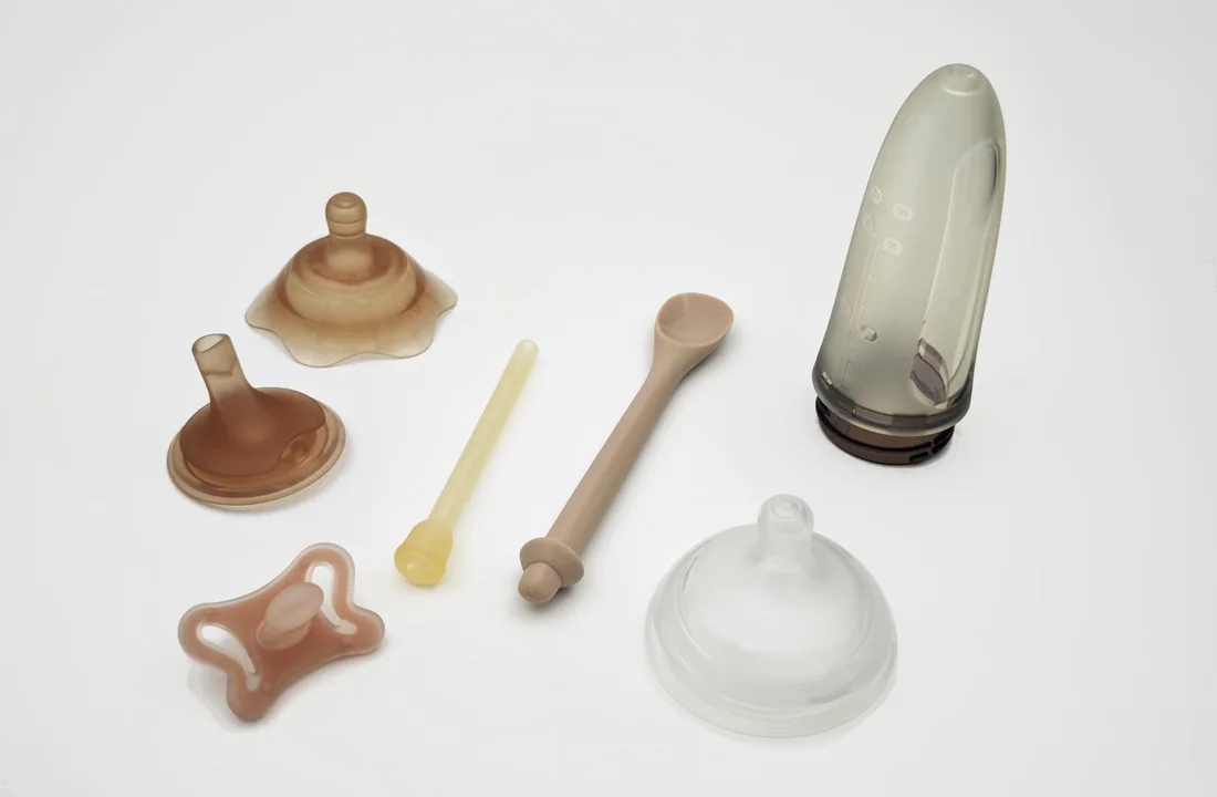
Silicone injection molded parts have a free shape and a working shape
A rigid molded panel is often discussed through its unloaded geometry. A flexible silicone component requires another layer of description: what changes when the part is installed. The perimeter can bend, a region can compress and a connection detail can stretch. The drawing and acceptance method should make clear which condition a particular requirement describes.
Suppose an equipment maker uses a silicone interface between two PC housing sections. The outside contour helps locate the part, but the closure arrangement determines how the working region is loaded. If the buyer measures only the loose component, a result can be accurate without answering whether the assembled interface behaves as intended.
A second project might use a flexible mask-shaped component that connects to a rigid structure. Here, the perimeter and the connection region perform different jobs. JY Pretech’s portfolio includes both separate silicone mask-shaped parts and a PC-plus-LSR assembly, making this a useful architecture to discuss. A new application still needs its own material, interface and acceptance definition.
A sealing perimeter needs its mating gap as well as its molded thickness
Identify the relevant surfaces of the rigid parts and the condition under which they close. The silicone’s local thickness belongs in that relationship, rather than being evaluated as an isolated dimension. If the housing can move within its own drawing limits, the customer should consider how those limits affect the flexible interface before demanding a tighter silicone tolerance.
The manufacturing team can then review the component geometry with a clear understanding of which regions control function. JY Pretech’s DFM and sample workflow provides the stage for discussing local wall thickness, gates, parting lines and trial acceptance before committing the next production step.
A silicone connection should have a defined installation movement
Show how the silicone detail passes over, into or around the rigid feature. A successful final position does not explain the loads encountered on the way there. Identify the direction of assembly and any edge the flexible material must cross. If the customer changes the rigid entry feature, the silicone installation should be reassessed even if the soft-part model remains unchanged.
When the part is intended to be removed for service, describe that movement separately. A component that can be installed once may require a different design evaluation from one removed repeatedly. The expected service action is a customer requirement to define, rather than a durability promise implied by the use of silicone.
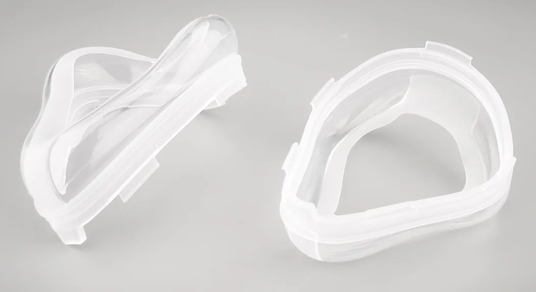
Hardness does not specify the force needed to close a silicone assembly
A hardness value is useful material information, but it does not describe the complete force response of a molded geometry. Thickness, shape, support and installed movement all contribute to what the assembly experiences. A loose plaque and a thin perimeter made from the same compound should therefore not be treated as equivalent functional samples.
JY Pretech lists LSR material references including WACKER ELASTOSIL LR 3003, SILASTIC LSR materials and Shin-Etsu KE G2000. The chosen full grade should follow the required function and current producer information. Our material capability list is a place to begin that review, rather than a declaration that every silicone component shares one hardness or performance envelope.
Compression behavior must be reviewed for the selected silicone construction
Where a component remains compressed, tell the technical team about the intended exposure and duty. The customer’s validation may need to consider the part after that condition, not only immediately after installation. The relevant requirement should be tied to the actual geometry, mating components and material proposal.
Shin-Etsu’s LIMS material information presents hardness and compression-set properties as distinct material data, with stated conditions. This distinction is useful background for a buyer: a hardness match alone is not evidence of identical behavior under sustained compression. Those producer data are not test results for a JY Pretech finished part.
The silicone contact face and the assembly locator can require different checks
A region that locates the part may be assessed through its geometry, while a contact region may require an installed evaluation. Put both requirements on the project brief so the sample review does not concentrate only on the easiest dimension to measure. The agreed method should explain the question each check answers.
This also helps a buyer investigate a returned component. Record whether the observed issue concerns location, closure, contact or visible damage, together with the installed configuration. A general complaint that the silicone is too soft can lead to a material change when the relevant issue is actually the supporting geometry.
The silicone injection molded parts manufacturer needs functional surface boundaries
JY Pretech’s LSR process covers tool creation, material preparation, injection, curing, demolding and subsequent operations. Before tool design, show where a parting line or gate location would affect the component’s use. For a flexible seal, the working perimeter deserves a different discussion from a hidden non-contact surface.
A parting-line witness should be evaluated in its actual location. On one region it may be an appearance issue; at another it may intersect an installed contact. Identify those zones and agree acceptance instead of applying one undefined cosmetic standard to every surface. The same approach should guide any trimming specified for the delivered component.
Gate and trim acceptance should reflect the silicone feature’s contact
If a gate vestige is permitted, show the region where it can remain and the accepted condition. Where trimming is included, review a representative sample after that operation. The buyer should accept the component it will receive, rather than a trial piece whose later finishing is still an assumption.
JY Pretech’s article on surface finish requirements in molding offers background on communicating appearance. A silicone sealing face still needs its own specific acceptance. A finish description intended for visual comparison does not establish the behavior of a flexible interface.
Define support and load when measuring flexible silicone dimensions
Agree the support and contact condition used for dimensional inspection. A flexible wall can move under a measuring load, so the chosen method should be appropriate to the drawing requirement. The acceptance record should distinguish a free-state observation from a measurement made on a fixture or installed assembly.
Do not turn an inspection fixture into an undocumented design constraint. If a support or fixture is needed, establish what it represents and how the part is placed in it. The customer and supplier should be evaluating the same condition when they compare results from different locations.
Separate silicone components and PC-plus-LSR assemblies solve different integration problems
A separately molded silicone part can be considered where the product architecture requires a distinct component and an assembly step. A combined rigid-flexible construction may deserve review where the interface is intended to be integrated. JY Pretech’s connected molding capabilities include thermoplastic injection molding, overmolding, LSR and assembly support, allowing the team to examine the required supplied object.
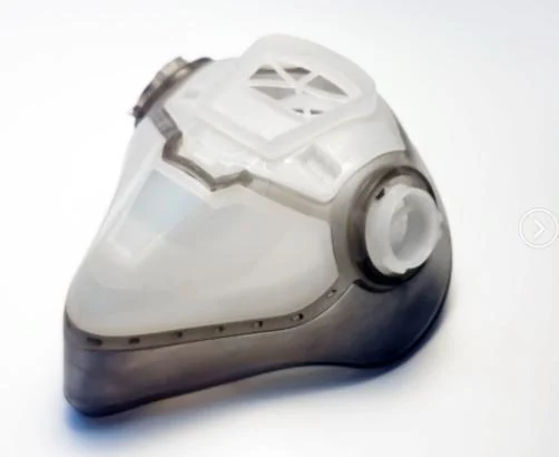
The integrated route should not be assumed to provide automatic adhesion, sealing or simplified service. Material compatibility, retention and the manufacturing sequence require review. Likewise, a separate part should not be rejected merely because it adds an assembly step; removability or independent replacement may be part of the customer’s design requirement.
Our range also includes compression molding for silicone and rubber components. If that route is proposed alongside LSR injection, compare the exact material and finished condition, not just the name of the process. A development sample in one construction cannot establish every requirement of a different production proposal.
Resolve the silicone drawing questions that often delay sample approval
A silicone release can stall when the team uses one sample approval to answer several different questions. The following distinctions help separate independent component acceptance, installed behavior and the material evidence required for a new device.
Can the molded silicone sample be approved without the rigid housing?
It can be reviewed for the features defined independently of the housing. Installed contact, closure and assembly behavior require the relevant mating condition. State the scope of a partial approval so a free-state dimensional release is not later interpreted as acceptance of the complete device interface.
Should a softer LSR grade be selected when the enclosure closes too tightly?
First identify where the resistance occurs and compare the silicone and housing versions with the released definition. A grade change is one possible technical decision, but it should follow a review of the geometry and installation. Otherwise it can alter other functions without resolving the cause of the closure problem.
Does a silicone mask example establish suitability for a medical device?
No. It illustrates a manufactured geometry. A new device requires the nominated material evidence, specified supplied condition and customer validation for its intended use. Any cleaning, special handling or sterilization responsibility must be agreed explicitly. A portfolio photograph is not a finished-device approval.
A rigid housing revision can change an unchanged silicone component
An equipment team may move a screw boss or alter a closure stop without touching the silicone drawing. Check whether that rigid change affects the installed gap or the path used to assemble the flexible detail. If it does, the unchanged silicone part number cannot by itself establish that the original application acceptance still applies.
Closure stops and silicone contact zones should be assessed together
Identify what establishes the final position of the rigid components. The flexible part should be reviewed within that intended arrangement, with the customer’s permitted variation considered. An assembly that closes differently because of a rigid stop should not be corrected by repeatedly changing the silicone shape without first understanding the relationship.
For a mask-shaped assembly, also show how the flexible part is located relative to the rigid connection. If the perimeter appears uneven after assembly, distinguish an actual molded-shape issue from an incorrect seating condition. Comparing the free component, its locating region and the assembled configuration gives the team more useful evidence than adjusting the perimeter from a single photograph.
A replacement request deserves the same care. Confirm whether the customer’s current housing matches the version used for the original silicone approval. A worn returned component may explain where a problem is visible, but the released geometry and installed requirement remain necessary for a new manufacturing proposal. This is particularly relevant when a buyer inherits the project from another team and has only samples available.
JY Pretech can review the molding and interface information the customer provides, then identify the geometry or process questions that need resolution before tooling or trial work. Keeping the rigid revision visible helps direct that work toward the actual assembly rather than refining an isolated silicone outline.
Protect the accepted silicone shape until it reaches the rigid assembly
A compliant perimeter should not be held in an unintended installed condition during shipment and then judged against a free-state reference without considering that handling. Explain the features at risk when the packing arrangement is agreed. The appropriate protection follows the part’s geometry, surface sensitivity and next assembly operation.
If the customer receives multiple silicone variants, keep the material and drawing identity clear. A visually similar replacement may have a different perimeter, connection or compound. Where those differences affect the installed relationship, the receiving instruction should direct the team to the correct component rather than relying only on appearance.
Approve the part with the rigid counterpart and the intended assembly movement in view. That gives JY Pretech a specific geometry to manufacture and a clear sample condition to document. It also gives your assembly team a useful answer to the original question: how this identified silicone detail is supposed to behave once it leaves the bench and becomes part of the product.