

 Get a Quote
A 3D Printed Metal Parts Manufacturer for Geometry That Still Has to Assemble
Combining several shapes into one metal component can simplify an assembly, but the bolts, locating faces and internal spaces still need a workable manufacturing plan. A 3D printed metal parts manufacturer should be evaluated around that completed component. The relevant question is whether complex geometry can be connected to the finished interfaces, material condition and evidence the equipment requires.
JY Pretech offers metal 3D printing with post-machining. Its selective laser melting, or SLM, route builds metal geometry from powder and connects it with operations such as support removal and machining of precision features. Industrial developers should begin with the intended component function, the approved material and the surfaces that must assemble with other parts. Our manufacturing capabilities provide the broader comparison with CNC and fabricated alternatives.
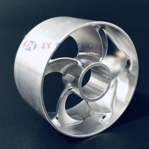
A 3D printed metal parts manufacturer should begin with the assembly interfaces
A complex body may be attractive to print, while its functional interfaces remain ordinary engineering requirements. Identify the mounting faces, holes, threads and locating geometry that determine assembly. These features should be defined on the drawing alongside the complex shape, rather than left for the supplier to interpret from the outside appearance.
A consolidated bracket still needs a defined mounting plane
Consider an equipment developer combining a bracket and several connecting features into one component. The integrated body may reduce the number of separate items to manage. Its mounting plane still needs to locate against the equipment, and the bolt pattern still needs an agreed relationship with that plane. Explain those requirements before treating the printed model as a complete manufacturing brief.
JY Pretech’s combined printing and machining service is relevant because the different regions can require different operations. The printed form may provide the overall geometry, while machining establishes a critical face or bore. The project should identify that sequence and the final supplied condition without assuming that every surface requires the same treatment.
Threaded holes should be identified as finished features
If a hole must accept hardware or locate another component, state its requirement and reference relationship. Do not rely on the visual presence of a hole in the model to define its final accuracy, thread or surface condition. JY Pretech specifically describes machining for precision holes and threads within its metal printing route.
A purchaser should also identify the installed hardware where it affects access or function. A fastener may need clearance for a tool, not merely space for its shank. A consolidated geometry that blocks assembly access can lose its intended benefit even if every individual feature can be manufactured.

Metal printing geometry must leave a feasible removal and finishing route
JY Pretech describes SLM as a metal additive route followed by relevant post-processing. The build creates a component within a powder-based process; it is not simply an unrestricted way to make every enclosed shape. Supports, remaining powder and later access need to be considered as part of the manufacturing proposal.
Internal spaces need a powder-removal discussion
An integrated component may contain a passage, pocket or enclosed region. Explain its function and discuss how unused powder can be removed and the relevant condition verified. An acceptable external appearance does not establish that a hidden region is clear or suitable for its intended use.
For an equipment part with an internal path, the product owner may need evidence beyond outside dimensions. Identify that need before manufacture. The supplier’s quoted verification scope should say what it establishes, and any additional application requirement should remain visible rather than be replaced with an unsupported cleanliness or flow claim.
Support removal should not compromise the functional surface
Metal builds can use supports that are removed afterward. Their location and access influence which surfaces need later work. Discuss the proposed arrangement around the component’s functional regions. A surface carrying a support connection may need a different finishing plan from an exposed region whose as-built condition is acceptable.
Renishaw’s metal additive orientation guidance provides primary technical context for considering the build arrangement. Its process principles help explain the review. They do not establish a machine model, build parameter or guaranteed result for a JY Pretech component.
Choose the metal designation before treating the geometry as released
The JY Pretech metal printing service lists 316L, 17-4PH, S136, ASSAB Corrax, Ti6Al4V and AlSi10Mg. These material routes serve different engineering requirements. State the approved designation and required condition, or identify the selection question that remains open. A broad request for a strong metal part is not a complete material specification.
316L and 17-4PH should be connected to their intended service
A component chosen primarily around corrosion exposure can present a different material decision from one chosen around another mechanical requirement. Review the exact designation and condition relevant to the application. Do not assume that the word stainless makes materials interchangeable or that a family name supplies every finished-part property.
Our metal printing material information provides a starting point for discussing the available families. The order should still identify the actual material basis and requested evidence. Other manufacturers’ published properties should not be substituted for an accepted specification or a verified result on this component.
Ti6Al4V and AlSi10Mg require their own geometry and condition review
These listed routes can be considered where the application justifies them. A proposal to change the material should also review the component’s function, finishing and acceptance requirements. Reusing the same outside model does not establish that every relevant property or operating assumption remains equivalent.
For the consolidated bracket, weight may be a project objective, but it should not be expressed as an invented saving. Compare the actual proposed component with the practical alternative. Any claimed improvement requires an appropriate basis and evidence rather than a percentage borrowed from an unrelated additive example.
Post-machining should be planned before the build is committed
JY Pretech’s service connects printed metal with CNC finishing where precision features require it. Identify the final component geometry separately from manufacturing stock and build preparation. The supplier needs a feasible way to locate and machine the required features, while the buyer needs a clear definition of the accepted result.
A mounting face and bore need a shared reference plan
If the bore locates another part relative to the mounting face, communicate that relationship on the drawing. A correct diameter alone may not establish assembly position. The machining and inspection plan should address the functional relationship rather than generate unrelated accurate features that still fail to work together.
The same principle applies to tooling components discussed in our printed mold component guide. The applications differ, but both need a connection between complex printed geometry and controlled final interfaces. A component’s purpose determines which relationships deserve particular attention.
Finishing access should remain available after consolidation
A design that combines several elements may make a previously accessible surface harder to machine. Review that access while the geometry can still be discussed. If a required feature is difficult to reach, identify whether a revised geometry or another manufacturing route would better preserve the function.
Protolabs’ metal printing design guide supplies general background on design and finishing considerations. The useful principle is to plan the complete route. Its numerical limits and material data belong to that producer and should not be presented as JY Pretech specifications.
For the integrated bracket: distinguish the shape printing creates, the interfaces machining must establish and the hidden condition that needs verification. Those three questions can determine whether the consolidation remains useful after manufacture.
Compare a printed body with a realistic fabricated or machined alternative
JY Pretech also describes CNC manufacturing and sheet metal fabrication. A relatively accessible solid component may suit machining. A formed enclosure or support may suit cutting and bending. A more involved integrated geometry can justify an additive review. Compare the actual alternatives rather than assume one process is always superior.
A bent support may solve the mounting task with simpler geometry
If the application mainly needs a support with accessible flanges and openings, a fabricated route may be worth reviewing. If the function depends on complex integrated features, printing may deserve more detailed consideration. State the required envelope and interfaces so the comparison protects useful function instead of preserving unnecessary complexity.
For an industrial buyer, the relevant scope includes finishing, inspection and the next assembly stage. A quotation for a bare build should not be compared directly with a machined or fabricated component supplied in its completed condition. The comparison becomes meaningful when the delivery objects are aligned.
Fewer separate pieces can change how the equipment is serviced
A consolidated bracket can remove joints or reduce the number of items handled during assembly, but it can also change replacement practice. If one feature is damaged, the customer may need to replace the integrated component rather than a separate small item. Identify that service requirement while comparing the proposed geometry with the original assembly.
For equipment used in several versions, integration can also connect features that previously changed independently. A mounting arm may remain common while a sensor interface varies. Review whether one combined shape is desirable across those versions or whether a separate interface remains more practical. The manufacturing choice should preserve the product’s actual configuration needs.
| Consolidation objective | Assembly question | Service question | Definition to retain |
|---|---|---|---|
| Remove a connecting joint | How the integrated body is located | Which object is replaced after damage | Mounting references and supplied component identity |
| Combine a bracket and sensor mount | Whether the sensor remains accessible | How different equipment versions are supported | Interface position and accepted variant |
| Enclose an internal feature | How remaining powder is removed | Whether inspection or cleaning access is required | Internal geometry and verification scope |
These questions do not argue against additive manufacture. They make the proposed improvement measurable through the work the component must support. JY Pretech’s combination of metal printing, machining and other manufacturing routes allows the buyer to discuss a complete component choice. Any reduced assembly work or improved service outcome should still be evaluated for the actual design rather than asserted from the process name.
A useful drawing review therefore includes the next technician as well as the first assembler. Show the hardware that must remain reachable and the item that a service team will identify later. That context can reveal whether the complex integrated shape is solving the right problem before the project commits to its final manufacturing route.
Accept the component through dimensions, condition and application responsibilities
JY Pretech’s quality review information provides a route for agreeing checks and records. Identify the critical dimensions and material evidence required by the order. A coordinate measurement can address suitable geometric relationships, while an internal condition or application requirement may need a separate agreed verification method.
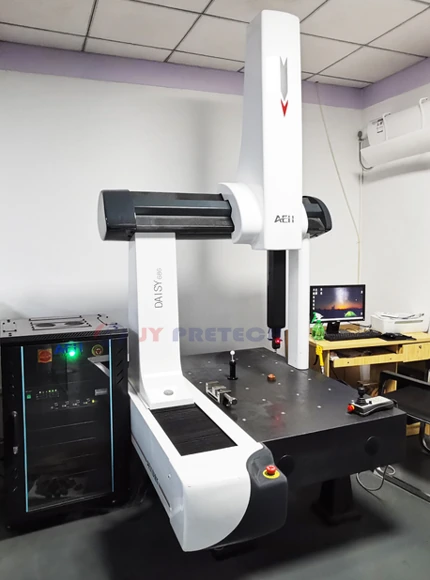
The final report should describe the actual supplied material and revision
Keep inspection records connected to the accepted geometry and completed manufacturing stage. If a treatment or machining operation occurs after an intermediate check, identify what evidence establishes the delivery condition. The buyer should be able to distinguish a build-stage result from acceptance of the finished part.
Agree protection for locating faces, exposed threads and any delicate geometry during delivery. The packing arrangement should follow the actual component and final surface condition. Confirm identification for similar versions so the receiving team can connect the delivered object with the approved drawing and records.
Before releasing the consolidated bracket, trace the mounting plane, bolt pattern, finishing access and internal spaces through the proposed route. Keep printing where it provides useful geometry, and define the operations needed to make that geometry assemble. The finished component should justify the process choice through its own requirements, not the complexity of its rendering.