

 Get a Quote
Where a 3D Printed Mold Components Manufacturer Fits in a Tooling Project
Metal printing can create a complicated shape, but the mold still needs that shape to locate, seal and work with the surrounding construction. A 3D printed mold components manufacturer should therefore be evaluated on the completed component route. Selective laser melting, or SLM, builds metal geometry layer by layer; machining and other agreed operations can then establish the interfaces that the tool needs.
JY Pretech offers metal 3D printing with post-machining alongside tooling and mold component supply. This combination gives a tooling buyer a practical basis for reviewing additive geometry and finished interfaces together. Begin with the component’s role in the mold, its material and supplied condition, and the features that must be machined or inspected. Printing is one stage of the decision, rather than the complete acceptance criterion.

A 3D printed mold components manufacturer should explain why printing helps
Not every tool component benefits from an additive route. An accessible block or simple insert may be more straightforward to machine. A component with more involved geometry can justify reviewing metal printing, provided the manufacturing plan also addresses supports, powder removal, treatment and final interfaces. The useful comparison concerns the whole component, not the novelty of the process.
Complex insert geometry should solve a defined tooling problem
Consider an engineer reviewing a compact insert with geometry that is difficult to reach by a conventional cutting tool. The first question is what function requires that geometry. If an accessible redesign preserves the function, machining may remain attractive. If the geometry provides a necessary feature, JY Pretech can review an additive-plus-machining proposal around the actual requirement.
A buyer should provide both the component definition and the assembly context. An isolated solid model may not show the surfaces that locate the insert, the neighboring tool elements or the reason a particular internal region matters. That information helps distinguish a meaningful additive application from a shape that could be simplified without losing useful function.
Printed geometry and machined seating faces have different jobs
The printed portion may establish a complex overall form, while machining establishes a seat, bore, thread or other critical interface. JY Pretech’s service explicitly connects metal printing with post-machining for precision features. Mark the surfaces that require a specified final condition. A single general finish instruction may leave the most important interfaces undefined.
For a tooling component, identify the references from which those interfaces are located. Our precision component drawing guide explains why the relationship between locating and forming surfaces matters. Additive manufacture does not remove that dimensional chain; it changes how the near-final geometry is created before the agreed finishing work.
Build the printed mold component around a complete post-processing route
JY Pretech describes powder and support removal, heat-treatment discussion, machining and surface treatments within its metal printing information. The required sequence depends on the component. Identify which operations are included and which final condition will be supplied. A printed shape awaiting substantial additional work is a different purchasing object from a component ready for the next tool assembly stage.
Support removal must remain possible around the tool’s functional features
Metal powder-bed builds can require supports that are later removed. Their location and access affect the manufacturing plan and can affect the surfaces that need subsequent work. Discuss those constraints before approving a geometry solely because it can be represented in CAD. A support that cannot be removed without compromising a required feature is a practical manufacturing problem.
The Protolabs metal printing design guide provides general background on orientation and support-related considerations. Use those principles to understand the route proposed for the component. Do not transfer another manufacturer’s numerical limits, material properties or machine capabilities into a JY Pretech specification.
Powder-removal access matters for enclosed or internal geometry
A model with an enclosed region can create questions about removing unused powder and checking the resulting condition. Explain the function of any internal geometry and discuss an appropriate manufacturing and verification approach. A visually convincing external surface does not establish the state of a hidden passage or cavity.
Internal cooling geometry is a topic to review specifically if it is proposed. JY Pretech’s published metal printing service establishes the additive route, but it does not establish a validated cooling design or a guaranteed thermal improvement for a particular mold. Any such project needs its own geometry, cleanability, verification and tooling-performance discussion.
That boundary protects a useful engineering opportunity. A buyer can investigate whether an additive feature provides value without turning an unreviewed concept into a purchasing promise. Define what the component must do, how it can be made and what evidence is needed before accepting the proposed route.
Select S136 or ASSAB Corrax from the actual tooling requirement
The metal printing service lists S136 tool steel and ASSAB Corrax alongside 316L stainless steel, 17-4PH stainless steel, Ti6Al4V and AlSi10Mg. These are distinct material routes. The presence of several metals in the service range does not mean that a convenient printing alloy is automatically appropriate for a mold component.
Tool steel designation and final condition should be agreed together
State the approved material and the condition required for the component’s work. If treatment is part of the proposal, identify its role and the acceptance evidence expected afterward. Do not infer final hardness, corrosion behavior or service life from a material name alone. A condition-dependent requirement belongs in the specification and the manufacturing scope.
The conventional tooling service also lists steels such as H13, S136, P20 and 1.2344. These references help establish the broader toolmaking context. A proposed change from a conventional route to printing should therefore include a material review, rather than assuming that any printed metal duplicates the original steel and its condition.
316L and AlSi10Mg are not generic substitutes for a tool steel insert
JY Pretech’s wider additive material range serves different types of custom metal components. A buyer considering a mold component should connect its material selection to the mechanical, thermal and surface requirements of that specific role. The ability to produce a geometry in a material does not establish its suitability for every use within a tool.
For general process understanding, the Protolabs Network metal printing guide discusses the importance of designing for the additive process and considering complete production cost. Its industry background supports the comparison; the actual material condition and project commitments should come from the agreed JY Pretech proposal.
Machining allowances should protect the interfaces you need to finish
A printed component intended for post-machining must be planned with that later operation in mind. Identify the final geometry separately from the manufacturing stock and explain which surfaces establish location during finishing. The buyer should approve the final requirement; the manufacturer should review a feasible route for reaching it.
Compare the insert’s complete route rather than the printing operation alone
A quotation for a build and a quotation for a finished insert can look similar while covering different work. Separate the operations needed to reach the accepted component. This is particularly important when an engineer is comparing an additive proposal with a machined construction that already includes the final interfaces.
| Reason for considering printing | Work that remains to be reviewed | Decision the drawing must support |
|---|---|---|
| Difficult overall geometry | Build orientation, supports and removal access | Which features are essential to tool function |
| Integrated internal features | Powder removal and an appropriate verification route | How the internal condition will be accepted |
| A complex body with precise mounting | Stock, fixturing and post-machining | Which final surfaces locate the component |
| A proposed material or condition change | Treatment and agreed material evidence | Which approved requirement the new route must satisfy |
For a small custom tooling order, this comparison can reveal that the build itself is not the main source of uncertainty. Finishing access or the condition of a hidden feature may decide whether the route is practical. Conversely, an integrated geometry may remove an awkward conventional construction and justify the extra planning. Evaluate that tradeoff against the actual component, rather than assuming printing is always either cheaper or more expensive.
JY Pretech’s combined service provides a place to review these linked operations. The project proposal should state which are included and what remains with the buyer or receiving toolroom. That scope makes the supplier comparison useful and keeps an attractive rendering from becoming the only evidence behind a tooling decision.
Final component definition: the installed geometry, material condition and accepted surface requirements.
Manufacturing preparation: the build arrangement, supports and stock needed to reach that final definition.
Seating faces and threads should be identified before the build is prepared
A locating face or threaded interface may need finishing after printing. Mark those requirements on the component drawing and explain their relationship to the surrounding tool. If the finishing route cannot access a critical region, identify that conflict during review. Adding a machining requirement after the build can be less useful than planning the route from the start.
For a buyer replacing an existing component, also establish whether the printed route is intended to reproduce the approved design or change it. Our replacement component discussion covers the uncertainty created by worn samples and missing records. An additive proposal should resolve those questions, rather than use a new process to reproduce an unidentified condition.
Accept the finished additive component with evidence suited to its role
JY Pretech’s inspection resources include coordinate measurement and projection methods. Agree the dimensions, profiles and reference relationships to be reported for the completed component. A surface that will be machined should be accepted in its final supplied condition, rather than judged only from the appearance of the initial build.
Hidden geometry can require a separate verification discussion. Do not assume that a routine outside dimensional report establishes an internal passage, cleanliness or a process-dependent material requirement. Identify what the supplier will verify and what additional application or tooling evaluation is needed. Keep unavailable evidence visible rather than replacing it with a confident claim.
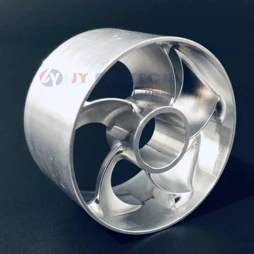
The published metal printing and machining example provides context for the combined service. It is not a certificate of suitability for every tooling application. A new mold component should have its own requirements and acceptance scope, even when it uses a familiar material or resembles an existing portfolio image.
A tooling trial should distinguish component fit from claimed process improvement
A component can fit the tool without establishing every intended production benefit. If the project aims to change thermal behavior, molding quality or another operating result, define that evaluation separately. The comparison needs agreed conditions and evidence. Installation alone should not be presented as proof of a performance improvement.
JY Pretech also offers prototype tooling and molding, giving buyers another route for discussing staged development. Define which part of the program concerns manufacturing the metal component and which concerns evaluating the molding result. Those connected scopes can be coordinated without pretending that one automatically validates the other.
Choose metal printing when the finished tool insert justifies the route
Compare printing, removal work, any treatment, machining, inspection and the next assembly stage with the practical alternative. For a simple accessible insert, conventional machining may be the clearer choice. For a more involved geometry, the additive route may deserve detailed review. The decision should preserve necessary function and account for the whole delivery object.
Agree protection for the surfaces that will locate or form the part and identification for any similar components. A finished seat and an unfinished build surface have different handling significance. The shipment should make the supplied stage clear, especially if the receiving toolroom will carry out further work before installation.
Bring JY Pretech a model that explains both the difficult geometry and the interfaces that must remain precise. Ask for a route that connects the printed form to the completed tooling component. That is the useful basis for selecting metal additive manufacture: a component whose manufacturing advantages survive finishing, inspection and installation in the tool.