

 Get a Quote
Why a Precision Mold Components Manufacturer Needs More Than a Tight Size Tolerance
A core insert can measure correctly across its outside width and still be wrong for the mold. Its seating face may establish the wrong position, a profile may refer to an unsuitable datum, or the required surface condition may be missing. For a precision mold components manufacturer, the task is to make the component’s functional relationships controllable, rather than attach the same tight tolerance to every dimension.
JY Pretech manufactures custom tooling and components for mold projects. Engineers preparing a new component set should review our mold components service with the assembly drawing, material condition and critical interface definition. Our measurement resources and engineering approach provide a basis for discussing suitable checks. Start with how the component locates and what it establishes in the finished tool.
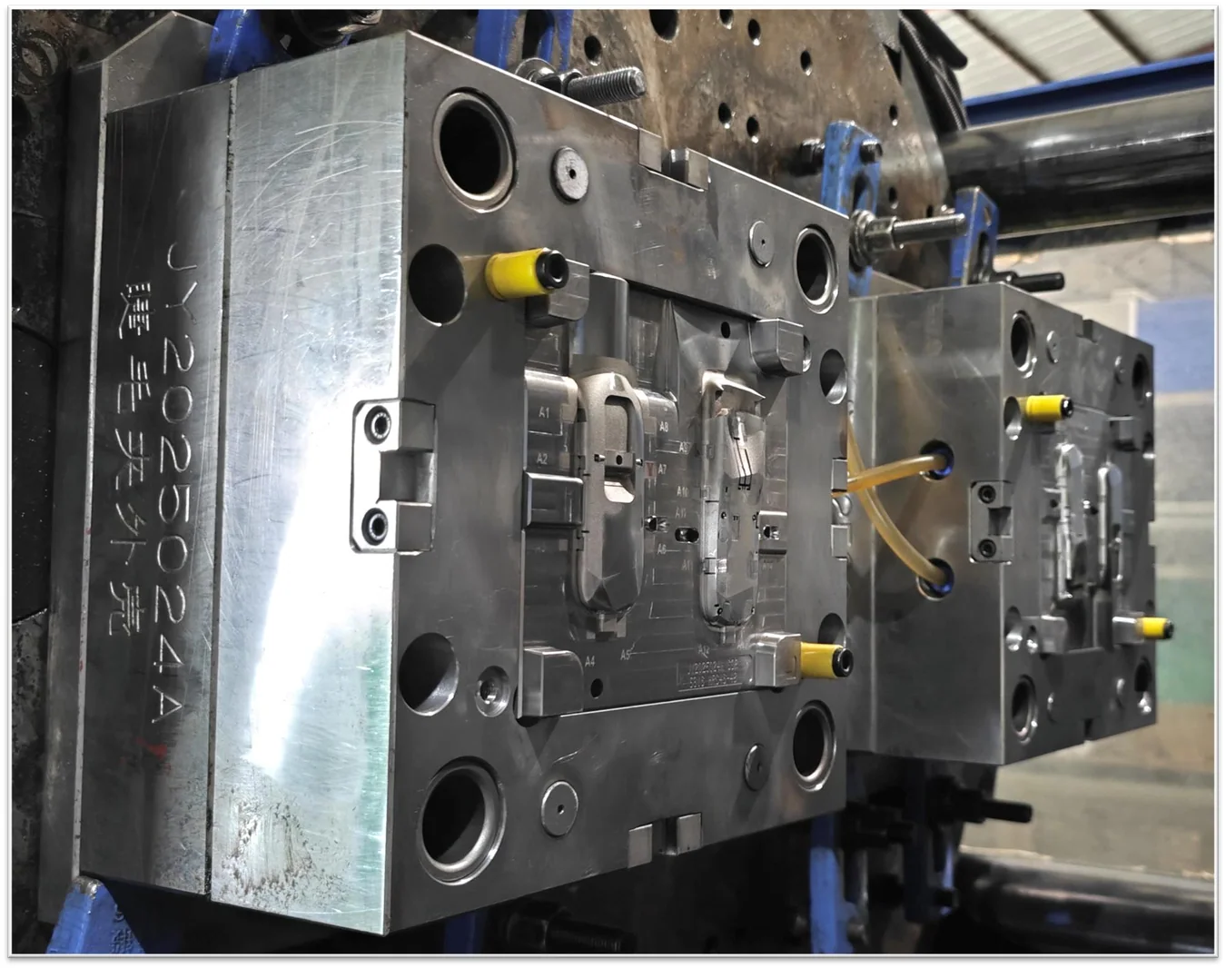
A precision mold components manufacturer should separate locating and forming surfaces
Locating surfaces establish where an item sits in the mold assembly. Forming surfaces contribute to the shape of the plastic part. They can belong to the same metal component while requiring different controls. A drawing that treats every face as an equivalent outside dimension can obscure the relationship that actually determines function.
A core’s seating face establishes the reference for its molded feature
Consider a core that forms a mounting boss inside an equipment housing. Its molded profile matters, but so does the position established by its seating arrangement. If the drawing does not relate those features coherently, a component inspection can miss the installed question. Identify the reference surfaces and the relationships that must remain correct when the core is assembled.
For a new tool, coordinate that definition with the surrounding construction. The core drawing should not contradict the assembly drawing or rely on an undefined mating condition. JY Pretech’s tool development process provides the broader route from customer requirements through tool review and sampling. Component precision should support that whole process, rather than exist as a separate purchasing claim.
Cavity profiles need tolerances tied to the plastic part’s function
A cavity region forming an exterior cosmetic surface can present a different priority from a region forming a critical assembly interface. Tell the manufacturer which features control product acceptance. That context helps distinguish requirements that need close dimensional control from those where appearance, release or another criterion is more important.
The distinction also helps avoid treating a tool component drawing as a complete molded-part guarantee. The tool establishes geometry within a molding process. Resin, cooling and release remain relevant to the resulting component. Agree how the tool measurements and molded samples will be used together to judge the project.

Precision mold component drawings should control the relationship that matters
A size dimension answers one question. Location, orientation and form can answer others. The buyer should define the requirements needed for the specific component instead of assuming that reducing a general size tolerance controls every possible error. Where a requirement is unclear, resolve it during drawing review rather than asking inspection to invent an interpretation.
Parallel faces and profile position are different inspection problems
For an insert supported between defined surfaces, the relationship between those surfaces can matter independently of the nominal thickness. For a shaped core, the position of the profile relative to its locating geometry may matter more than an unrelated external width. Explain the intended function so the drawing and measurement scope address the same question.
This is a technical specification discussion, not a recommendation to impose every available geometric control. Unnecessary requirements can make manufacture and inspection harder without improving the product. Identify the relationships that affect the installed mold and the plastic component. Leave other dimensions at an agreed level appropriate to their purpose.
| Component region | Reason for control | Evidence to agree |
|---|---|---|
| Locating seat | Establishes installed position | Dimensions and relationships to defined references |
| Plastic-forming profile | Creates the required component geometry | Suitable profile or dimensional checks and subsequent sample evaluation |
| Shutoff interface | Works with a specific mating region | Agreed interface geometry and installation review |
| Visible molded-surface region | Contributes to product appearance | Defined metal finish and molded appearance reference |
A shutoff requirement must identify the mating geometry
A shutoff region works as an interface. Give the manufacturer the information needed to understand its counterpart and the intended assembled condition. A standalone drawing with an unexplained critical face can be insufficient. If the mating component is also new, coordinate the pair; if it is retained, identify the definition on which the new supply relies.
Our replacement mold component guide examines the additional uncertainty created by worn or undocumented existing items. A newly manufactured component set offers the opportunity to establish those relationships deliberately. Do not import the ambiguity of a maintenance sample into a new drawing package.
Specify mold steel condition alongside the dimensional requirements
JY Pretech’s export tooling information lists H13, S136, NAK80, 1.2343, 1.2344 and P20 among its steel options. These names support a project discussion but do not describe identical materials or conditions. State the approved designation, any required treatment and the evidence expected with the component.
H13, S136 and P20 are not a substitute for a supplied-condition note
The material requirement should relate to the component’s work in the mold. If a buyer specifies a grade but leaves the supplied condition open, quotations can represent different scopes. Identify the required state and the point at which dimensions and surfaces are accepted. The manufacturer should not have to infer these decisions from a general description such as “precision hardened insert.”
JY Pretech identifies hardness measurement among its inspection resources. If hardness is part of acceptance, agree the requirement and checking scope. Do not assume a single unspecified reading establishes every property of a component. Material identity, treatment, geometry and surface condition need a coherent definition for the intended tool.
A steel change proposed during the project should be reviewed as a change to the approved requirement. Explain the reason and identify any effect on the agreed manufacturing or inspection scope. A familiar alternative is not automatically equivalent simply because it can be machined to the same outline.
Final inspection should refer to the accepted manufacturing stage
If the route includes treatment or a later surface operation, identify the condition in which dimensions are accepted. An intermediate machining result is not automatically evidence about the final supplied component. The buyer and manufacturer should agree which checks belong before subsequent work and which establish the delivery condition. This prevents an accurate but incomplete report from being interpreted as final acceptance.
For a precision core, a locally polished forming region and a locating surface can have different roles after machining. The approved process should preserve the relationships defined on the drawing. If further work is expected at the receiving toolroom, distinguish that unfinished delivery object from a component supplied ready for installation. The quotation and report should refer to the same object.
This distinction can also explain apparently inconsistent quotations. One supplier may include the final finishing and agreed checks, while another prices a machined blank for later completion. Compare the included operations before comparing the tolerance statements. JY Pretech’s tooling and measurement services can be discussed within the required scope, but the buyer should make the intended supplied stage explicit.
Polished cavity regions and textured regions need different finish references
JY Pretech lists high-gloss, polished and VDI or Mold-Tech texture options. Define the treated regions and the reference used to accept them. A polished forming surface, a seating face and a hidden clearance surface do not necessarily need the same treatment. Applying one vague finish note to the entire component can create unnecessary work or an unresolved appearance expectation.
Our molding finish discussion is relevant when tool finish must support a visible product surface. The metal component’s appearance is not the only acceptance object. Agree whether molded samples are needed to assess the resulting cosmetic condition and which process stage that approval belongs to.
Choose mold component inspection by accessibility and reference geometry
The company profile identifies 3D coordinate measurement and 2D projection equipment, alongside other inspection resources. Those methods offer different ways to examine geometry. The drawing should make clear what must be established so the inspection plan can address the feature, its access and its relevant references.
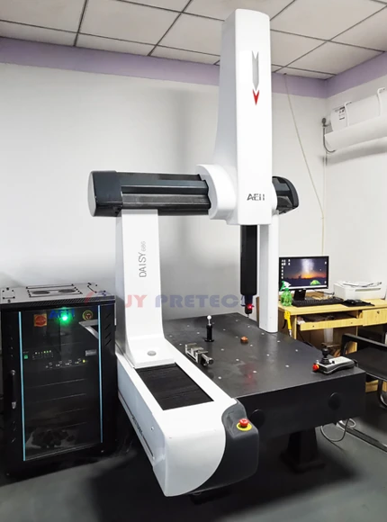
A coordinate report should show which datums establish position
A list of measured values without an identifiable setup can be difficult to interpret. For the core that forms a housing boss, the useful report should relate the profile to the specified locating references. Agree the reporting scope and any fixture assumptions before inspection. This gives the receiving engineer a basis for comparing results rather than simply comparing file names.
If a feature is difficult to access directly, discuss that limitation while the component and inspection plan are being reviewed. A different method, a defined intermediate check or additional agreed evidence may be needed. Do not turn an inaccessible requirement into a confident measurement claim without explaining how it is established.
Access also matters during manufacture. A deep internal region and an exposed outside plane do not offer the same tool approach. When the critical requirement concerns a difficult feature, explain its function and review the proposed route before assuming that any shape in the model is equally straightforward to produce. That discussion should preserve necessary function while identifying unnecessary difficulty in the drawing.
A buyer may find that a local geometry revision allows a clearer manufacturing and inspection plan without changing the installed interface. Alternatively, the feature may be essential and justify the additional work. The correct decision depends on the tool’s function. It should be made deliberately during engineering review rather than emerging as an unexplained exception when the component is ready to ship.
Projection checks can complement the plan for suitable profiles
A visible profile can present a different measurement task from a spatial relationship between several surfaces. The availability of projection and coordinate methods supports a feature-specific discussion. Neither should be chosen only because it is familiar to purchasing. Identify the actual geometric question and the evidence the receiving team needs to accept it.
General machining guidance from Protolabs on CNC tolerances explains why selected critical requirements are more useful than indiscriminately tightening a whole drawing. Apply that engineering principle to the JY Pretech component definition; do not import another manufacturer’s published tolerances as promises about this order.
Release the precision component as part of a controlled tool assembly
For an initial component set, identify the assembly, individual part numbers and revisions. If two items must be assessed together, state that relationship. If the receiving plant performs the installation, clarify what the supplier checks before dispatch and what remains to be confirmed in the installed tool.
Protection should follow the critical surfaces. A finished cavity profile, a sharp locating edge and a general outside face can have different handling needs. Agree the arrangement for the actual component set, including identification where similar inserts could be confused. A dimensional result is only useful if the accepted surfaces reach assembly without avoidable damage.
For a development program, JY Pretech’s rapid tooling options can be reviewed around changing geometry and the next trial. For a released production tool, the component definition may need a more settled replacement and maintenance record. Identify the stage so the supply proposal matches the work the component must support.
When the drawing review returns to the original core insert, trace its plastic-forming profile back to the seat that locates it. Then ask whether the material condition, surface requirement and inspection method support that relationship. JY Pretech can discuss a precision component around that coherent definition. A tighter outside width alone cannot complete it.