

 Get a Quote
Custom CNC Machined Parts Manufacturer: Make the Drawing Work at the Machine
The housing model contains a narrow deep pocket, sharp internal corners and a threaded opening behind another feature. Each is easy to draw, but the manufacturing route needs physical access. A custom CNC machined parts manufacturer should understand which features are essential to function and which can be revised. A useful engineering handoff preserves the part’s job while making the proposed cutting and inspection route clear.
JY Pretech describes CNC work for parts, tooling and mold components in its manufacturing capabilities, alongside post-machining for printed metal. Begin with the current model, a dimensioned drawing, material, quantity and critical interfaces. The project should identify the final component rather than leave the supplier to infer function from a solid shape.
A custom CNC machined parts manufacturer needs the feature’s function
A narrow pocket can hold a required component or simply reflect an early packaging choice. A sharp corner can be essential to a mating relationship or unnecessary in a clearance region. Explain those differences. The manufacturer can review access more usefully when it knows what must remain fixed and what geometry is open for discussion.
Internal pocket corners should match the mating requirement
Rotating cutting tools create a relationship between internal geometry and tool access. A drawing with sharp enclosed corners can require review rather than an assumption that every model feature is straightforward to mill. Identify the component that occupies the pocket and the clearance needed around it. A local radius or other approved geometry change may preserve the function.
Do not revise a required locating corner solely to simplify the quotation without considering the assembly. Instead, show the mating definition and ask for a practical route. The objective is an accepted component that works in the equipment, rather than a more convenient shape that no longer locates the intended item.
Deep pockets need a review of access, not only outside dimensions
A pocket’s depth, width and surrounding walls affect the manufacturing discussion. A tool must reach the region and perform the required operation without an unexplained obstruction. There is no useful universal answer based only on the part’s overall size. Provide the actual model and identify the surfaces that require particular accuracy or finish.
For an equipment housing, a broad opening may lead to a narrow region beneath another feature. That geometry deserves attention before a release is treated as routine machining. A designer can often distinguish a functionally necessary region from a feature inherited from an earlier concept, giving the review a concrete basis.
Custom CNC parts manufacturing should connect the model with the dimensioned drawing
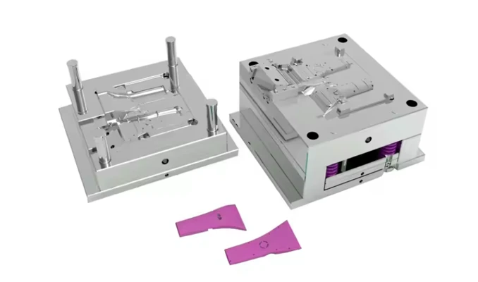
JY Pretech’s project handoff information identifies STEP or IGS models and dimensioned drawings as useful inputs. The model communicates the solid geometry, while the drawing identifies critical references, tolerances and notes. Keep both at a coherent revision so the proposal addresses the part the buyer intends to release.
A mounting face should establish the references used by critical holes
If a hole locates a component relative to the housing’s mounting face, express that relationship. An isolated diameter does not establish position in the assembly. The manufacturer needs enough information to review how the relevant features will be produced and checked against the same functional definition.
Our precision component drawing guide discusses locating and forming relationships in tooling. The same engineering principle is relevant to a custom machined part: the reference should describe how the component works, rather than an arbitrary surface selected because it is easy to dimension.
Thread specifications should include the connection the part must provide
Identify the required thread and relevant feature definition instead of leaving a modeled opening unexplained. State where the connection sits relative to the mounting arrangement and whether a later treatment affects it. The supplier should not have to infer a final thread requirement from the visual appearance of a cylindrical hole.
Access for the installed fastener matters too. A thread can be manufacturable while the assembled equipment leaves no practical way to tighten or remove its hardware. Show the surrounding context where that affects function. This keeps the manufacturing review connected to the real assembly and service action.
Review machining access before making the housing more integrated
A design can combine several features into one part while making one region harder to reach. Explain the reason for integration and compare it with the finishing route. JY Pretech’s portfolio includes conventional CNC work and metal printing with post-machining, providing related routes to review where the geometry justifies them.
An added boss can obstruct a previously accessible pocket
If a revision adds a mounting boss near a pocket, review more than the boss itself. The change can affect tool approach to a neighboring surface. Provide a short description of the revision so the supplier can identify the relevant access issue instead of treating the new model as an otherwise identical part.
For a housing still in development, identify the features already fixed by mating hardware and those that remain flexible. That distinction allows a manufacturability discussion to focus on realistic alternatives. It does not imply that every change is inexpensive or that an accepted earlier route remains suitable after a substantial redesign.
Consider the insertion path of the item carried inside the pocket. A component may fit its final modeled position but be unable to pass through the opening after the surrounding bosses are added. Supply an assembly view showing how it enters and seats. The machining discussion can then preserve the required access for both manufacture and installation, instead of resolving only one of those problems.
For example, an equipment developer may need a replaceable internal block to slide against a locating wall. The opposite wall might only provide clearance. Marking that difference allows the review to concentrate accuracy on the working location and discuss an approved opening change elsewhere. This is a proposed engineering scenario, not a claim that a particular wall can always be removed or that the part can be machined in a single setup.
If the housing uses a separate cover, include its attachment relationship rather than sending the base model alone. A screw boss near the pocket can affect the available space for the internal block and its fastening tool. JY Pretech’s combination of custom component and tooling work is relevant to reviewing these connected features, but the buyer still needs to approve any design revision before manufacture proceeds.
A printed body can still need reachable machined interfaces
JY Pretech’s metal printing service specifically discusses CNC finishing of precision holes and threads. If the broader shape is better reviewed as a printed body, retain the final machining requirement. Additive manufacture does not remove the need for access to establish the critical final interface.
Protolabs’ machining design toolkit provides primary background on considering geometry and cutting access together. Its principles help frame the review. Its stock materials, machine limits and published tolerances are not JY Pretech specifications and should not be inserted into the order as assumptions.
Use real material requirements without assuming a universal CNC catalog
State the approved material and supplied condition for the actual component. JY Pretech’s CNC work spans custom parts and tooling, but the quotation should confirm the material and route proposed. A broad capability description should not be interpreted as a stocked list of every alloy or a guarantee for every geometry.
Tool steels in mold projects need their own component definition
The tooling service lists options including P20, H13 and S136. Those designations are relevant to particular tooling discussions, not interchangeable labels for every machined part. If the order concerns a mold component, identify its locating geometry, forming role and required condition alongside the material.
A custom industrial housing can present a different material decision. Provide the product owner’s actual requirement and relevant exposure or mechanical conditions. The supplier can review the proposed manufacturing scope without implying that a familiar tooling material automatically suits an unrelated component.
A material substitution should be reviewed before the geometry is treated as unchanged
If another designation or condition is proposed, identify the reason and the requirements needing approval. The same model does not establish the same finished-part behavior in every material. Keep the change connected to the application, finishing and acceptance plan rather than treat it as a purely commercial adjustment.
For a printed intermediate component, retain the exact additive material and final condition through its machining order. A machine shop receiving the item needs an understandable definition of what it is finishing. The final drawing and the intermediate delivery record should describe compatible stages of the same component.
Specify critical machining requirements where they improve the part
Not every dimension requires the same emphasis. Identify the interfaces that control assembly, the surfaces that carry appearance requirements and the regions that mainly provide clearance. This helps keep the manufacturing and inspection scope tied to the part’s actual function rather than an unexplained demand for maximum precision everywhere.
A clearance pocket and a locating bore require different acceptance evidence
The pocket may primarily need space for a neighboring component, while the bore establishes position. Describe those different jobs. A tighter general tolerance on every surface is not a substitute for identifying the particular relationship that determines whether the assembly works.
General guidance from Protolabs on CNC tolerances explains the value of selecting critical requirements deliberately. Apply that reasoning to the current component without copying another supplier’s numerical capability claims. The accepted JY Pretech scope should identify the actual requirements and evidence.
For the housing review: mark the mating features, tool-access concerns and dimensions controlling installed position. A short explanation of those three groups can be more useful than tightening every number on the drawing.
Plan inspection around the completed machined interfaces
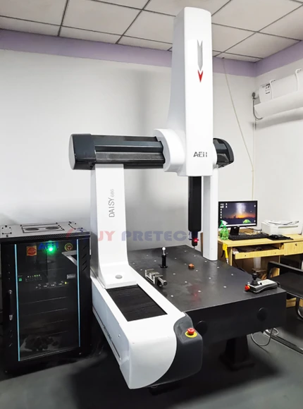
JY Pretech’s quality review information and company resources provide a route for discussing suitable checks. Agree the dimensions and records needed for the component, including the relevant references. A list of measurements should identify the accepted part and the final stage it describes.
Coordinate measurement should answer the actual datum relationship
For a mounting face and bore, the useful result is their defined relationship, not merely separate size values. Identify the references and any relevant restraint or setup condition. The receiving engineer should be able to understand what the measurement establishes without reconstructing an unexplained fixture arrangement.

Surface work should not leave final fit undefined
If coating, marking or another operation affects the supplied condition, identify it before release. JY Pretech’s broader capabilities include associated finishing and assembly-related work, subject to project review. Confirm the actual operation and any protected interface rather than assume it is included for every machined component.
For a thread or locating face, state whether the final requirement applies after all relevant work. An intermediate machining report can be useful without proving the completed delivery condition. Keep that distinction clear when several operations are coordinated within the project.
Release the machining route with the housing’s access problem resolved
Agree identification and protection for finished faces, threads and any delicate features during delivery. The receiving team should be able to connect the component with its current drawing and use it at the intended next operation. The method should follow the actual geometry rather than a universal packing assumption.
Before releasing the housing, revisit its deep pocket, internal corners and threaded connection. Identify which geometry is essential, which can change and how the accepted interfaces remain reachable. The final handoff should show a component that works in the assembly and a manufacturing route that can physically reach the features defining that function.