

 Get a Quote
Precision CNC Machining Supplier Decisions Before Tightening Every Tolerance
A bore can meet a demanding diameter requirement while sitting in the wrong place relative to the mounting face. For an engineer selecting a precision CNC machining supplier, that distinction matters more than a broad promise of accuracy. Start by defining the relationships that make the component work, the condition in which they apply and the evidence needed to accept them.
JY Pretech’s custom manufacturing capabilities include CNC work for components and tooling. Its quality resources support discussion of dimensional inspection. A component with a critical bore, locating face or threaded interface should arrive for review with a current solid model and a dimensioned drawing that explains those features together.
Give the precision CNC machining supplier a functional dimension chain
The first question is how the component establishes position in the equipment. A mounting face, locating bore and fastener holes can perform different jobs. Their acceptance requirements should reflect those jobs. A collection of individually tight dimensions does not necessarily describe the relationship that the assembled mechanism needs.
A locating bore needs a reference beyond its diameter
Consider a machined block that supports an alignment feature. The bore size affects its mating relationship, but the bore’s position and orientation relative to the mounted block may also control the result. Identify the surfaces that establish the block’s installed position. Otherwise, the supplier can check size without receiving a complete definition of functional alignment.
This is particularly useful when the buyer supplies a STEP or IGS model with few drawing notes. A solid communicates geometry, but the critical relationship still needs an explicit requirement. Explain the assembly function using a section or mating view where necessary, then agree how that requirement will be evaluated.
A mounting face should represent the way the block actually seats
A convenient measurement surface may differ from the face used in the machine. If a component seats on a particular face, identify it clearly and explain relevant contact conditions. The chosen references should let the manufacturer and receiving engineer describe the same installed relationship instead of creating two internally consistent but different interpretations.
Our precision mold component guide discusses a related problem in tooling, where locating relationships affect how parts work together. For a machined industrial block, use the actual equipment interface rather than adopting a mold-component convention merely because the supplier also makes tooling.
Precision CNC machining requirements should distinguish size, position and surface
A tolerance attached to a size does not automatically control every characteristic of the feature. A surface appearance note does not establish its geometry. Review what each requirement is intended to prove. This keeps a quotation focused on the actual manufacturing and verification work instead of an undefined demand for a generally precise part.
| Component relationship | What the buyer should define | What a separate size reading may miss |
|---|---|---|
| Bore locating an assembly element | Diameter and the required relationship to mounting references | Whether the element sits in the intended position |
| Face seating against equipment | Relevant surface geometry and final supplied condition | How the component contacts the mating structure |
| Fastener connection | Thread definition, access and relationship to mating holes | Whether hardware can connect the complete assembly |
| Visible external region | Appearance requirement separated from functional interfaces | Whether a cosmetic expectation was part of acceptance |
The table describes questions to resolve, not a universal inspection package. A simple mounting block and a forming insert do not necessarily require the same checks. JY Pretech can review the component in the context of its custom manufacturing scope, while the agreed drawing remains the basis for the particular order.
A threaded hole should be accepted as a connection
State the thread requirement and its relationship to the component’s installed location. If later treatment or assembly affects that connection, identify the final condition. Checking an intermediate opening before all relevant operations may leave the receiving team with evidence that does not answer whether the delivered connection is usable.
Cosmetic machining marks need their own acceptance language
If an external face is visible in the finished equipment, distinguish that appearance expectation from the dimensions controlling assembly. A photograph or agreed sample can help define a visual requirement when appropriate. Avoid treating an attractive machined surface as proof of the bore’s alignment, or a dimensional report as proof of a particular appearance.

Agree how the critical CNC features will be measured
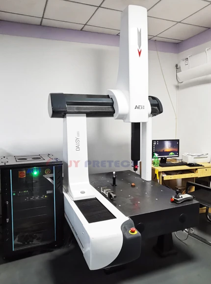
JY Pretech’s inspection resources include coordinate measurement and optical projection. The useful discussion is which method can establish the component’s required characteristic in its relevant condition. Equipment names alone do not prove that every internal feature, surface or assembled relationship can be inspected in the same way.
Coordinate measurement should follow the block’s accepted references
For the locating bore, connect the reported result to the references on the drawing. Identify the feature and the requirement being assessed. A receiving engineer should be able to follow the report without guessing which face was used to establish position or whether the measured part matches the released revision.
If a component needs restraint during measurement, describe the intended condition and why it matters. An unsupported thin region can behave differently from the same region held in the final assembly. The inspection agreement should resolve that issue for the actual geometry rather than assume every part should be clamped or every part should be measured free.
Projection is useful only when it can resolve the specified profile
Optical projection can support suitable profile checks, but an obstructed feature or a three-dimensional relationship may call for another approach. Explain the characteristic requiring evidence before selecting the instrument. A tool list is a starting point for a feasibility review, not an interchangeable set of methods producing identical answers.
For a small tool insert with an accessible outline, the profile may be an important acceptance subject. For the mounted block’s bore relationship, a different measurement arrangement may be relevant. Keeping those examples separate helps the buyer specify useful records instead of asking for every available inspection method on every order.
Keep the final material condition in the precision component definition
Dimensions describe a particular object in a particular state. If a component will undergo treatment, finishing or machining after an earlier check, state which results apply to the completed delivery. JY Pretech’s tooling and component service and metal printing with post-machining involve different routes that need their own final-condition definition.
A tooling insert and a printed metal body need different process records
A tooling discussion may involve listed steels such as H13 or S136 and a forming or locating function. A printed metal body can require support removal and machining of precision holes or threads. Neither route should inherit an unspecified inspection stage from the other merely because both finish with a machined interface.
For the printed body, connect the supplied intermediate condition with the final machining requirements. For the tooling insert, define the required component condition and mating relationships. The buyer can then ask whether the proposed evidence addresses the finished item rather than an earlier operation that is easier to measure.
Finishing must preserve the interface the drawing intends
If a coating or other surface operation is included, identify the regions whose fit or contact must remain controlled. Confirm the proposed treatment and any protection needed for a critical bore or seating face. Do not infer a particular coating capability or masking method from a broad reference to finishing.
An integrator receiving a finished component needs the final interface to work without an unplanned rework step. Explain that next operation when reviewing the order. It gives the supplier a concrete reason to distinguish a finished locating surface from a region where appearance is the main concern.

Use a prototype to resolve uncertain CNC requirements
A development order can reveal whether a proposed interface definition actually matches the assembly. The useful result is a clearer engineering decision, rather than a blanket instruction to make every dimension tighter on the repeat order. Record which characteristics influenced assembly and which did not.
For example, an equipment team may find that mounting position governs alignment while an outer clearance wall has ample space. The next drawing revision should preserve the former relationship and avoid adding unnecessary restrictions to the latter. That revision needs approval; a supplier should not silently relax a released requirement after interpreting a trial.
Protolabs’ discussion of machining tolerances provides general background on choosing requirements deliberately. Its numerical limits and service conditions do not establish JY Pretech capability. Use the engineering principle to ask a better question about the current component, then confirm the actual proposed scope.
Separate assembly proof from the CNC measurement report
A successful trial assembly and a dimensional record answer related but different questions. The trial shows how the selected components behave together under its particular conditions. The record can establish specified characteristics of the machined part. For the locating block, agree which evidence is needed instead of assuming either one automatically replaces the other.
A mating trial should identify which block and counterpart were used
An engineering team trying a prototype block with one mating item may learn that the combination fits. That does not establish how the block will behave with every permitted counterpart. Retain the identity and relevant revision of both pieces, and compare the result with the intended interchangeability requirement. A useful development trial should help refine the drawing rather than create an undocumented matched pair.
If the component is intended for a particular assembly only, make that requirement explicit too. A paired supply arrangement differs from an interchangeable spare. JY Pretech’s made-to-drawing component work allows the acceptance discussion to start with the buyer’s real requirement; it does not make one of those supply models the automatic default for every precision order.
Report labels should distinguish the bore’s size from its location
A row of unlabelled numbers can conceal which characteristic was checked. Refer each important result to the drawing feature and requirement, including the relevant unit and reference system. For the block, a bore-size entry and an entry describing its positional relationship should remain understandable as different pieces of evidence. The buyer should not have to infer that distinction from similar values.
Where the prototype exposes disagreement between a trial fit and the dimensional record, first review identification, revision, measurement condition and the definition of the mating interface. Tightening an unrelated external dimension is unlikely to resolve an unexplained discrepancy. The next action should address the characteristic responsible for alignment, with the revised requirement agreed before the next component is produced.
Release the precision order with evidence that answers the alignment question
JY Pretech’s custom project process provides a route for exchanging model, drawing and project requirements. Where geometry itself needs revision, the machining-access discussion helps separate an unreachable feature from a poorly specified one. These are connected reviews, but tightening a tolerance does not solve either problem automatically.
For the mounting block, agree identification and protection of the bore and seating face through delivery. A correct measurement has limited practical value if the critical interface is damaged or the report cannot be matched to the received revision. Define the relevant records and protection around those actual features rather than impose unrelated documents or packing rules.
The release question is specific: can the delivered bore establish the intended relationship when the block sits on its mounting face? If the drawing, proposed process and inspection plan all answer that question, the precision requirement has a purpose the buyer and manufacturer can share.