

 Get a Quote
Precision Sheet Metal Parts Supplier: Control the Dimensions Across the Bends
Each flange on a formed panel can appear acceptable in isolation while the final mounting holes still miss the equipment chassis. An engineer selecting a precision sheet metal parts supplier should define the installed relationships that matter, including how the panel is supported during acceptance. Tightening the flat drawing alone may leave the actual assembly problem unresolved.
JY Pretech provides custom sheet forming through cutting, punching and bending, with joining and finishing discussed for the project. Its inspection resources include coordinate measurement. Start with the formed model and a dimensioned drawing identifying the mounting references, critical holes and final condition the buyer needs to receive.
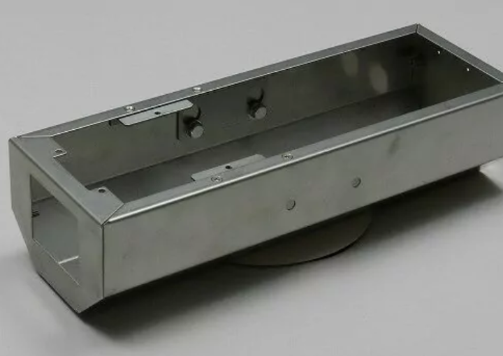
A precision sheet metal parts supplier needs the installed reference system
A component’s position in the assembly should guide the critical dimensional definition. Identify the face that seats, the features that locate and the remaining points that provide fastening or clearance. The supplier can then review the relevant manufacturing and verification route against a coherent function rather than a disconnected collection of dimensions.
Mounting holes on opposite flanges share an assembly requirement
For a U-shaped panel mounted to a chassis, a hole on one side may need a controlled relationship with the corresponding hole on the opposite flange. Show that relationship in the formed condition. Separate local dimensions to bend lines may not communicate the final hole pattern the chassis must accept.
Consider an equipment builder using an existing chassis whose mounting points cannot move. Those fixed interfaces should be identified before the panel is released. A supplier suggestion to change a flange or slot can then be evaluated against the retained hardware rather than accepted simply because it makes one fabrication step easier.
A seating face should establish the intended panel position
A broad sheet region may contact the equipment only at selected locations. Explain the intended seating arrangement and any relevant support condition. Choosing an arbitrary edge as a measurement reference can produce understandable local results without proving that the panel sits in the correct place when attached to its actual structure.
Where the part is flexible, identify whether acceptance applies free or under a defined mounting condition. Do not leave the inspector to create an undocumented restraint that makes the component look satisfactory. The buyer and supplier need a repeatable interpretation of the same requirement, with any fixture or support condition described clearly.
Precision sheet metal dimensions should distinguish cut features from formed relationships
A cut hole and a hole’s location after bending are different subjects. Cutting establishes features in the blank; forming establishes their spatial relationship across bends. A drawing that applies one unexplained requirement to both can conceal the operation that actually determines the fit. State the required finished relationship instead of relying on a generic precision label.
Hole-to-bend requirements need the actual formed geometry
Show the relevant bend and the hole’s function. If a hole is close to a formed region, the manufacturer needs the actual geometry and material information to review the proposed route. Avoid adopting another supplier’s universal spacing rule without confirming its relevance to the accepted JY Pretech process and component.
The sheet service discusses V, U and channel forms. Those families can have different access and sequence questions. A mounting feature on a return flange should be reviewed as part of that complete form rather than treated as an isolated cutout that has no relationship to the next bend.
Several acceptable bend relationships can still produce an unacceptable span
If the mounted panel must bridge a fixed distance, define that completed relationship directly where appropriate. Do not assume that separate flange lengths and angles always explain the assembly requirement clearly enough. The drawing review should identify how permitted variation in the relevant features affects the final span and mounting arrangement.
Protolabs’ sheet tolerance discussion provides general background on differences between fabrication operations. Its numerical capability ranges do not establish JY Pretech limits. Use the underlying process distinction to identify the characteristic needing agreement on the actual formed component.
A locating hole and a clearance slot permit different assembly movement
If the design uses one feature to locate the panel and another to accommodate assembly variation, identify those roles explicitly. A slot is not simply an easier hole to manufacture. Its direction, surrounding material and relationship to the fastener affect the component’s function. The equipment engineer should approve that arrangement against the intended mounting and operating requirements.
For the U-shaped panel, a proposed slot on one flange might make installation less sensitive to a particular variation while leaving another relationship unchanged. That possibility needs review with the chassis definition. The supplier should not introduce it as an undocumented correction after a trial, and the buyer should not assume that additional clearance is acceptable wherever a hole fails to align.
Enlarging the mounting holes can hide a formed-envelope error
A panel can clear its fasteners yet still sit outside the intended equipment envelope. If a prototype fails to mount, compare the complete formed geometry with the accepted requirements before changing the openings. The error may involve a seating relationship, flange position or another characteristic that a larger hole would leave unresolved.
For example, a removable cover must clear neighboring components as well as accept its screws. Enlarging the screw holes may allow installation while moving the cover into a nearby component’s space. Treat the fit problem as an assembly relationship: identify what must locate, what may float and what clearance must remain. Then revise the relevant drawing with those decisions visible.
This gives JY Pretech a specific manufacturing question to review. The proposed correction can be evaluated against the formed part and its mounting function, rather than judged only by whether the first trial can be fastened in place. Retain the approved change in the released definition before the next panel is ordered.
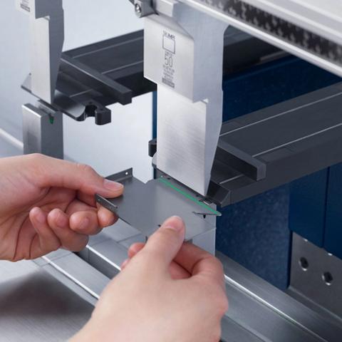
Agree the measurement condition before accepting the formed panel
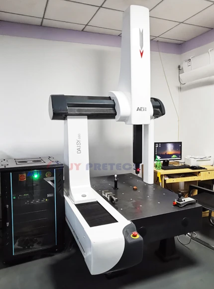
Inspection should answer the requirement the equipment uses. For a thin panel, how the part is supported may be relevant to the result. Discuss the actual geometry, critical characteristic and proposed method. A coordinate measuring system is a resource for suitable checks, not proof that every panel should be restrained or measured in the same way.
A free-state panel and a mounted panel can answer different questions
A free-state check can describe the supplied item without installation forces. A defined mounted check can address a particular functional relationship. If both are relevant, identify their separate purposes. The accepted plan should avoid using an undefined assembly force to conceal an unresolved shape issue while also avoiding a free-state requirement that misrepresents the intended function.
For a removable equipment panel, the buyer may care about locating the fasteners without forcing the part into place. Explain that practical requirement and the mating hardware. The supplier can review what the drawing and inspection should establish rather than infer the allowed installation effort from a nominal model alone.
Coordinate results should retain the agreed panel references
For opposite mounting holes, identify which reference establishes position and what relationship is being evaluated. Label the report so the receiving engineer can connect the result to the drawing. A list of coordinates without a clear reference definition may be difficult to compare with the intended equipment interface.
JY Pretech’s project questions and reporting information discuss inspection records and drawing inputs. Confirm the particular report required for this panel, including revision and component identity. Do not assume that requesting every available record provides better evidence than selecting the checks that establish the critical formed relationships.
Keep material and secondary operations inside the formed-part review
JY Pretech lists aluminum 5052 and 5754, stainless steel 304 and 316L, mild steel 1018 and copper C110 for sheet work. The selected material, thickness and condition belong in the accepted component definition. A change to those inputs deserves review alongside the bend geometry rather than being treated as a harmless purchasing substitution.
A material change should trigger a review of the accepted bend route
If another designation or condition is proposed, confirm its relevance to the part’s forming and application requirements. The same CAD shape does not prove that every material can follow the same route or meet the same final relationship. The buyer should approve the actual alternative before the order proceeds on a revised basis.
For a prototype that will establish the repeat-order definition, keep the material identity visible in the trial record. An acceptable panel in one material is useful evidence for that trial; it is not automatic proof for a later substitution. Any comparison should retain the inputs and final condition associated with the observed result.
Welding and finish can change which inspection stage matters
Where several panels are joined, define the critical mounting relationships after the included joining work. Where a surface operation affects the interfaces, define the relevant completed condition. A correct measurement of an earlier loose panel may remain useful without proving the final enclosure meets every requirement.
The fabrication scope guide discusses how an order can end at different stages. Precision requirements should follow the same supply boundary. If JY Pretech is supplying loose formed parts, specify that endpoint; if the order includes a joined and finished assembly, identify the final relationships to be accepted.
Use the first panel to investigate the actual fit discrepancy
A development panel can reveal a mismatch between the drawing’s local dimensions and the equipment’s installed requirement. Investigate the actual discrepancy before applying tighter limits everywhere. Identify the part, revision, material and check condition, then compare the observed mounting issue with the requirement that was originally specified.
A chassis trial should identify the mating hardware and constraint
An equipment team may find that the holes align when a panel is heavily restrained but not during normal installation. Record the relevant condition and clarify the intended acceptance requirement. The trial should reveal whether the drawing communicates the real function, rather than provide an unexplained demonstration that someone can eventually force the fasteners into place.
Conversely, if a flexible panel is designed to locate against defined supports, a measurement taken in an unrelated condition may not answer the installed question. The solution is a clear agreed definition. It should explain the intended support and feature relationship without allowing arbitrary manipulation to determine the acceptance result.
A local machining analogy cannot replace the sheet tolerance review
Our CNC precision discussion also separates size, references and function, but the manufacturing route differs. Do not copy a machining tolerance block onto a bent panel without reviewing what forming and the selected material can support. Ask for acceptance of the actual sheet requirements, with any exceptions resolved before manufacture.
JY Pretech’s multiple manufacturing routes allow a wider component discussion where needed. A feature may be reviewed as a separate machined item if the construction justifies it, but that is an engineering change with joining and acceptance consequences. It should not be an unspoken workaround for an unresolved sheet drawing.
Preserve the mounting geometry through the receiving stage
For the U-shaped panel, identify the flanges and edges vulnerable to unintended bending during delivery. Agree protection and separation appropriate to the actual part and finish. A suitable dimensional report should remain connected to a component whose critical mounting geometry has been preserved, rather than arrive as evidence for a shape altered during handling.
JY Pretech’s company information provides context for its custom manufacturing work. For this precision order, the decisive evidence remains specific: an accepted formed drawing, a defined measurement condition and results addressing the mounted relationships. Resolve the cross-bend hole pattern before release so purchasing receives a usable panel instead of several individually acceptable dimensions.