

 Get a Quote
SLM Metal Parts Manufacturer: Decide the Build Around the Surfaces That Matter
Rotating a metal component in a build can make one region easier to support while moving another functional surface into a less convenient position. An SLM metal parts manufacturer needs to understand which surfaces control the component’s use. SLM means selective laser melting, a metal powder-bed additive route. Its build arrangement should be reviewed with removal, machining and acceptance in mind.
JY Pretech’s metal printing and post-machining service connects that additive route with finishing operations for relevant interfaces. An engineering handoff should identify the material, critical faces, internal geometry and final supplied condition. Start with the surfaces that must locate, mate or remain accessible, then review how the proposed build reaches them.
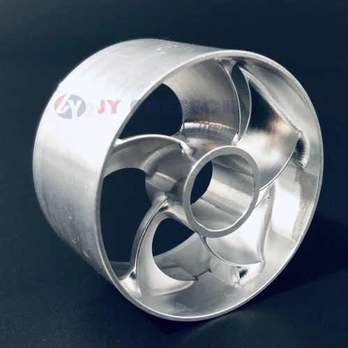
An SLM metal parts manufacturer should know which surface establishes function
A component’s largest face is not necessarily its most important reference. A small mounting region can determine its installed position, while the broader curved body mainly occupies space or provides another function. Mark those roles on the drawing. The build proposal should protect the relationships that matter rather than optimize an unexplained outside shape.
A curved metal body can still locate from a simple mounting face
Consider an industrial component with a curved body and a machined mounting interface. Its complex form may justify reviewing SLM, but its installation still depends on the reference face and connection features. Explain how that interface works with the equipment. The manufacturer can then discuss orientation and subsequent operations against a concrete final requirement.
JY Pretech’s portfolio includes complex metal component examples. They illustrate the manufacturing route rather than establish the function or validated performance of a new design. A buyer should provide its own drawing and use requirements, even when the general shape resembles a portfolio image.
Holes and threads need their relationship to the mounting reference
The service describes machining for precision holes and threads. Identify which features require that final work and how they relate to the component’s locating geometry. The printed opening alone does not communicate the final thread, position or surface condition required by assembly.
For a component carrying several connections, also consider access for assembly tools. A hole may be geometrically present but difficult to use after installation. Keep that practical access requirement in the engineering brief so a build arrangement does not solve manufacturing while leaving the assembled product awkward to work with.
Selective laser melting orientation should be reviewed with support removal
Metal powder-bed builds can require supports that are later removed. Their placement can affect access and the condition of adjacent surfaces. The engineering task is to connect the build arrangement with the final component, including where later machining or surface work is needed.
Support contact on a functional face needs an agreed finishing route
If the proposed arrangement places support contact near a mounting face or another critical region, ask how the completed requirement will be achieved. It may be appropriate to plan machining or another agreed operation. The important point is to identify that work before the build is treated as the final delivery object.
Renishaw’s orientation guidance provides primary background on considering build arrangement in metal additive manufacture. It helps frame the questions. It does not supply JY Pretech machine parameters or establish that one orientation is universally correct for every alloy and geometry.
Removal access matters around recessed and enclosed regions
A support inside a difficult region can present a different finishing problem from one on an exposed surface. Explain why the geometry is required and review the proposed removal route. A CAD image cannot establish that every temporary structure will remain practically accessible after the build.
The same review should consider unused powder. Internal spaces need an appropriate removal and verification discussion. If a passage has a functional or cleanliness requirement, state it explicitly. An outside dimensional report does not automatically establish the condition of an unseen internal region.
Alternative orientations can favor different regions of the same metal part
For the curved component, compare candidate arrangements against the important features rather than count supports alone. An arrangement that leaves a mounting region convenient for later machining may place another region in a less accessible position. The supplier should explain the complete route for each practical option and identify the feature that drives the preference.
| Region controlling the decision | Orientation review | Required follow-through |
|---|---|---|
| Mounting face | How the build leaves material and access for finishing | A defined final reference and machining plan |
| Recessed connection | Whether support contact and removal remain accessible | A route that preserves the accepted interface |
| Internal passage | How the arrangement affects powder-removal access | An agreed internal-condition verification scope |
| Visible curved region | Which surfaces require later appearance work | A confirmed surface treatment and reference |
These comparisons do not establish a universal build angle. They identify the evidence needed to choose an arrangement for this geometry. A buyer can then understand why the proposal favors one route without relying on an unsupported promise that fewer supports or a shorter-looking build automatically produces the best finished part.
The same logic applies when a design is revised after an early sample. If a new connection becomes the critical feature, a previously useful arrangement may need review. Retain the final component requirements as the controlling target and allow the manufacturing discussion to respond to the changed geometry. The accepted proposal should identify the route for the current revision.
For an industrial project, this is a practical way to use the supplier’s process knowledge while keeping product decisions with the engineering owner. JY Pretech reviews the manufacturing route; the buyer identifies the function that must be preserved. An orientation decision becomes meaningful when those two responsibilities meet at the same drawing.

Plan SLM post-machining before the component leaves build preparation
JY Pretech combines metal printing with post-machining where required. The final drawing should identify the accepted geometry, while manufacturing preparation establishes the stock and arrangement needed to reach it. These are connected definitions, but a buyer should not confuse the intermediate build with the finished part.
A finishing setup needs usable locating features
Discuss how the component can be supported and located for its later machining operations. A complex body may not offer the same straightforward holding arrangement as a simple block. The proposed route should make the critical final relationships achievable without asking the buyer to infer an unexplained setup.
For a curved component with a final mounting face, identify which surface or feature establishes position during finishing. If a subsequent bore depends on that face, keep the relationship visible in the drawing. A correct bore size does not by itself establish the installed position of the component.
Machining stock should support the final surface requirement
If material is intentionally left for later work, distinguish it from the accepted final geometry. The required stock is a manufacturing decision to review with the supplier, not a reason to alter the final requirement without approval. State whether JY Pretech or the receiving organization performs that finishing stage.
Our finished metal-print supply guide examines that delivery boundary. An engineering orientation review should produce enough clarity that purchasing can request the correct stage, rather than compare an intermediate build with a component already machined to its final interfaces.
Mark the face that locates the component before discussing the orientation that builds it.
The material condition belongs in the SLM engineering release
JY Pretech lists 316L, 17-4PH, S136, ASSAB Corrax, Ti6Al4V and AlSi10Mg within its additive service. The grade and required condition should be identified before the route is approved. A general label such as metal does not establish the requirements for treatment, finishing or acceptance.
316L and Ti6Al4V builds should not inherit unexplained assumptions
Changing a material can change the engineering basis of the component. Review the intended exposure, mechanical requirements and final condition rather than assume that an identical model creates equivalent performance. The material information is a starting point for the project, not a universal property guarantee.
Our metal material information can support that discussion. If the product owner has already selected a designation, retain it in the order and identify the evidence required. An alternative should be reviewed as a technical decision with defined approval responsibility.
Heat-treatment requirements need a defined final acceptance point
The additive service discusses heat treatment as a possible part of the route. Agree what operation applies and which condition the component must meet at delivery. Do not infer a particular hardness or mechanical result merely from the name of a treatment or from another manufacturer’s material table.
Keep dimensional acceptance connected to the completed manufacturing sequence. If significant work occurs after an intermediate check, identify the evidence establishing the final supplied state. This helps the receiving engineer interpret a report without reconstructing the order of operations from separate files.
Surface requirements should distinguish appearance from fit
JY Pretech describes blasting, polishing, plating and machining among relevant post-processing options. The correct combination depends on the component. A visible outer region and a precision mounting interface can require different acceptance methods. State which surfaces carry which requirements rather than apply one vague finish description to the entire model.
A visible curved surface needs an appearance reference
If appearance matters, identify the region and the reference used to judge it. A general instruction to improve the surface may not tell the supplier what the buyer expects. The selected treatment should be confirmed for the material and geometry, with its effect on functional regions considered as part of the review.
A polished exterior does not replace a dimensional requirement at a mating face. Conversely, a dimensional report does not establish the desired visible appearance. Keep those approvals separate enough to be meaningful while ensuring they refer to the same completed component.
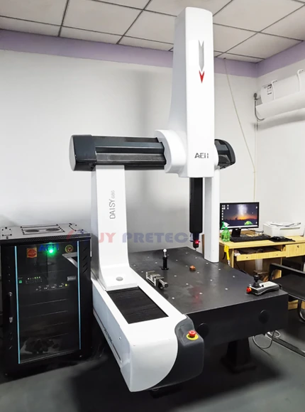
Record the build decisions that affect the accepted component
JY Pretech’s quality review information provides a route for agreeing checks and project records. The buyer should identify the relevant dimensions, material evidence and any special internal-condition verification. The record should explain the component it accepts, rather than list results without a usable revision reference.
A revised mounting face can reopen orientation and finishing decisions
If the designer moves a mounting region or changes a recessed feature, identify the change clearly. The supplier may need to review its effect on support access or later machining. A new model file should not be treated as an otherwise identical build merely because its overall envelope looks familiar.
Retain the accepted final geometry alongside the agreed supply scope. If an early sample is evaluated before every operation is complete, identify that limitation. A successful fit observation on an intermediate item should not silently approve a different finished condition.
Prototype quantities should represent a defined engineering decision
A small metal-print order may support geometry, assembly or material evaluation. State which question the samples must answer and which requirements remain open. Our prototype and supporting manufacturing capabilities provide several routes to discuss, but the trial’s purpose should determine the useful supplied object.
For general design context, Protolabs’ metal printing design guide discusses the connection between additive geometry and later work. Keep its numerical guidance within that producer’s scope. The JY Pretech proposal should identify the actual route and commitments for the component being ordered.
Before the engineering release, highlight the mounting reference, required threads, internal regions and surfaces affected by support removal. Ask for a build and finishing proposal that addresses those marked features. The most useful orientation is the one that reaches the accepted component through an understandable manufacturing route, rather than the one that merely looks convenient on screen.